
Author: Farid M, https://embeddeddesign.org/
In this tutorial, I am going to show you how to use AXI GPIO IP peripheral to control GPIOs on your Xilix Zynq FPGA. In the previous tutorials, I used AXI4 IP to control GPIOs, but it is in fact not necessary to use AXI4 if the application is just to interface with GPIOs. Thus, instead we use the built in peripheral AXI GPIO.
In this AXI GPIO demonstration, I will create two AXI GPIOs: one for input IOs: which will be the push down buttons on the Zedboard development kit, and the other AXI GPIO for output IOs, which will be the red LEDs on the Zedboard. When the user presses one of the push buttons, the corresponding LED will turn on, and display message on the serial port will say the button number pressed and the LED number that just turned on. I will be using five push buttons and five LEDs.
Like what we did in the past tutorials we need to follow the steps below:
- Create a new project for Zedboard, name it and save it.
- Create a Block design and name it.
- Add an IP and select ZYNQ Processing System.
- Run Connection Automation.
- From the IP catalogue, select AXI GPIO and add it .
Adding AXI GPIO
First, I will create an AXI GPIO for the input GPIOs. To do that let’s take the following steps:
- Select Add IP from the IP catalog under Diagram menu.
- Double click on the IP and click on IP configuration.
- Select: all Inputs, GPIO width equal: 5.
- Select GPIO Board Interface and set it to: btns_5bits. Then, click OK.
- Run Connection Automation.
Below are images showing what you expect to see when you are done.
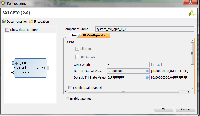
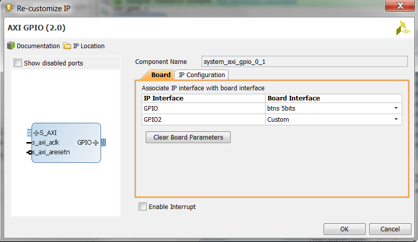
Figure1: GPIO Inputs configuration
Second, I need to add the AXI GPIO for the red LEDs. To do that, follow with me the steps below:
- Select Add IP from the IP catalog under Diagram menu.
- Double click on the IP and click on IP configuration.
- Select: all Outputs, GPIO width equal: 5.
- Select GPIO Board Interface and set it to: custom. Then hit OK.
- Run Connection Automation.
- The output signals will be automatically named to gpio_rtl. I renamed them to Leds_5Bits. You can do that by doubling clicking on gpio_rtl and then rename them under External Properties interface. Below is images showing what you expect to see:
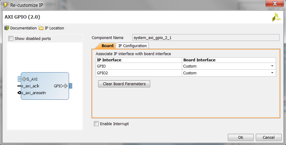
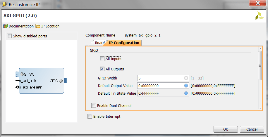
Figure2: GPIO Outputs configuration
After you run Connection Automation, and run Generate Layout, you can select Validate design and eventually your system diagram should look like the screen shot below:
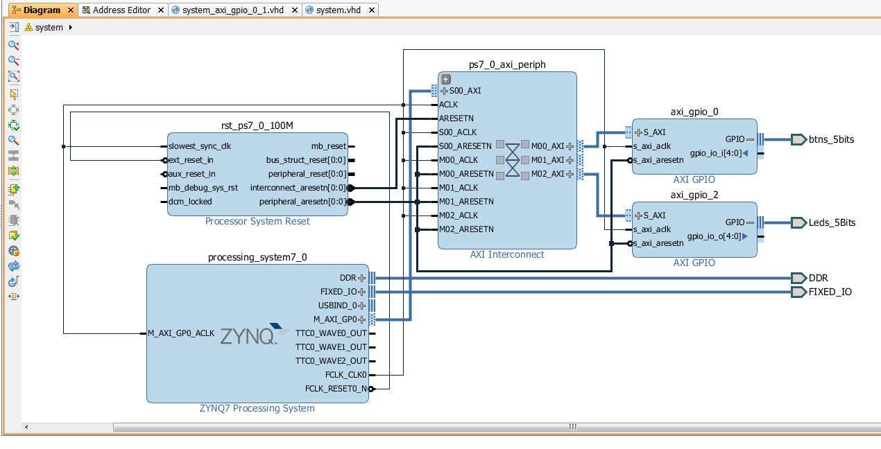 Figure3: Overall System Diagram
Run Implementation
Under Implantation menu, select run implementation and when it is completed successfully, open the implementation, and select I/O Planning instead of Default layout. What we need to do here is to assign pins to the custom output GPIOs that we added to the output AXI GPIO. At the bottom configuration bar, select I/O Ports, and start assigning pins under leds_5Bits_tri_o. The screen shot image below shows the correct pin assignments:
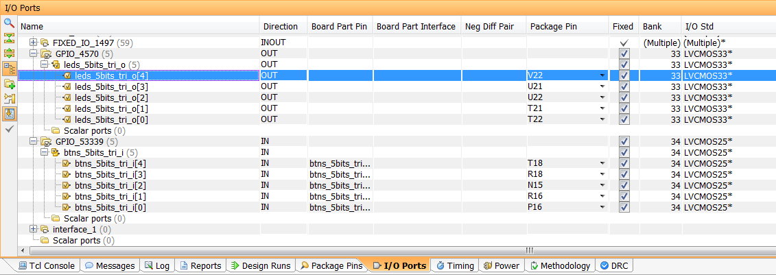 Figure4: GPIOs pin assignment
I could have selected the builtin configuration of the red LEDs, as part of the Zedboard kit, but I selected the GPIOs to be custom so that you know how to assign pins for custom made FPGA boards when you need to add an AXI GPIO.
SDK Project
Once you generated the Bitstream file, you need to export hardware, including Bitstream file, and then launch your SDK project. Then copy and paste the following source code in the Hello.c file. Also you can rename this file as well. I renamed this file: AXI_GPIO.c.
/*****************************************************
AXI GPIO Demo
Author: F.Mabrouk
****************************************************/

#include <stdio.h>
#include "platform.h"
#include <xgpio.h>
#include "xparameters.h"
#include "sleep.h"

int main()
{
XGpio input, output;
int button_data = 0;

XGpio_Initialize(&input, XPAR_AXI_GPIO_0_DEVICE_ID); //initialize input XGpio variable
XGpio_SetDataDirection(&input, 1, 0xF); //set first channel tristate buffer to input

XGpio_Initialize(&output, XPAR_AXI_GPIO_2_DEVICE_ID); //initialize output XGpio variable
XGpio_SetDataDirection(&output, 1, 0x0); //set first channel tristate buffer to output

init_platform();

while(1){

button_data = XGpio_DiscreteRead(&input, 1); //get button data

XGpio_DiscreteWrite(&output, 1, button_data); //write switch data to the LEDs

//print message dependent on whether one or more buttons are pressed
if(button_data == 0b00000){} //do nothing

else if(button_data == 0b00001)
xil_printf("button 0 pressed, and LED 0 is ON !\n\r");

else if(button_data == 0b00010)
xil_printf("button 1 pressed, and LED 1 is ON !\n\r");

else if(button_data == 0b00100)
xil_printf("button 2 pressed, and LED 2 is ON !\n\r");

else if(button_data == 0b01000)
xil_printf("button 3 pressed, and LED 03is ON !\n\r");

else if(button_data == 0b10000)
xil_printf("button 4 pressed, and LED 0 is ON !\n\r");

else
xil_printf("multiple buttons pressed, and multiple LEDs are ON\n\r");

usleep(200000); //this is the scanning interval for push buttons

}
cleanup_platform();
return 0;
}
Now we need to run the demo. To do this, you need to follow the steps below:
- Build your SDK project code,and make sure it builds successfully with no errors.
- Connect the serial port USB cables to your PC. Fore more info you can refer to my previous tutorial here.
- Select the right port for serial communication on Tera Term terminal.
- Select the baud rate to 115200. Refer to this link for more info.
- Program the FPGA.
- Run your code by selecting Run As: Launch on Hardware.
Below are my results as seen on Tera Term terminal, and on the FPGA:
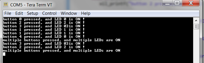 Figure6. Tera Term Results Display
Conclusion
As it can be seen, we have implemented two AXI GPIO peripherals for the control of push buttons and red LEDs on the Zedboard development kit. It is certainly a straightforward process. Whenever possible, you can take advantage of using this peripheral in your FPGA designs.
Author: Farid M, https://embeddeddesign.org/
If you find any of the projects posted here helpful to you while working on similar projects, or you learned something from any of the topics discussed, please do not hesitate to make a donation, whatever amount you can afford, just as a gesture of appreciation and to keep this website alive and progressing so that its benefits extends to many younger engineers and students around the globe.

Thanks for tor this tutorial! I found it helpful.
LikeLike
my pleasure
LikeLike
Thanks for tor this tutorial! It was very helpful
LikeLiked by 1 person