
In this post, I will be sharing with you an antenna design project I worked on in collaboration with the Radio Science Lab at the University of British Columbia. The goal was to design a low profile ultra wide band antenna with a gain of at least 8dBi, and a radiation efficiency higher than 90%. The frequency of operation of the designed antenna was 28 GHz, and it was designed to support a wide frequency spectrum bandwidth, extending from 20 GHz to 40 GHz

The antenna was used as a single element in a circular array that was deployed as a beam-forming scanner to detect angle of arrival for wireless signals with maximum power. This antenna aimed to be a novelty solution to multi-path fading, allowing for easy and reliable connections among wireless phone users, and increasing the rate of data transfer.
The Vivaldi antenna was introduced in 1979 in the IEEE European Microwave Conference paper by P. J. Gibson in a paper entitled The Vivaldi Aerial [1]. The antenna in such a paper was described to theoretically have an unlimited bandwidth. Also the antenna is an end-fire. The size of the antenna, the type of feed used, and dielectric material and thickness are variables that affects the performance of the antennas and its parameters such as gain, radiation pattern and reflection coefficient.
Theory of Operation
The figure below shows a standard slot tapered Vivaldi antenna:
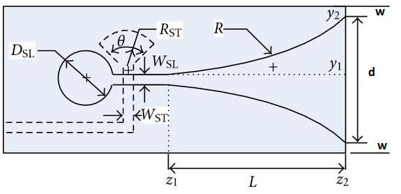
Figure1: Slot Tapered Vivaldi Antenna
The curves, denoted by R above, are defined by the following equation for two points, A1(x1,y1) and A2(x2, y2), along the curve [2]:
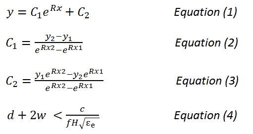
C1, C2, and R are user defined constants, and Equation(4) is used to set the high frequency fH.
It is important to note here that it has been verified by many studies that the feed part of the antenna determines its high frequency, while the end aperture size determines the low frequency [3]. In addition, the antenna shape and the dimensions determine the beam-width, side lobes, and back lobe radiation. Moreover, most Vivaldi antennas developed currently are half based on empirical methods, as there is no detailed theory that can be used as step by step guide in designing such an antenna [3].
Design and Implementation
The antenna design was based on this paper[4], and it was fabricated on a 0.787mm thick RogersRT/Duroid 5880 substrate with a dielectric constant of 2.2 and loss tangent of 0.0009. The geometry structure of the antenna is shown in Figure [3].
The proposed antenna was designed, simulated and optimized using High Frequency Structural Simulator, HFSS. This software is a powerful tool for simulating 3-D full-wave electromagnetic fields. It is a high accuracy, advanced solver. It is used extensively by most RF and antenna engineers for designing high-frequency and high-speed electronic components.
The design geometry discussed in [4] and shown in Figure[2] was my starting point in the design process. I modified the dimensions shown in Figure[2] as well as the ground plane before achieving an optimum design that meets the design specifications.
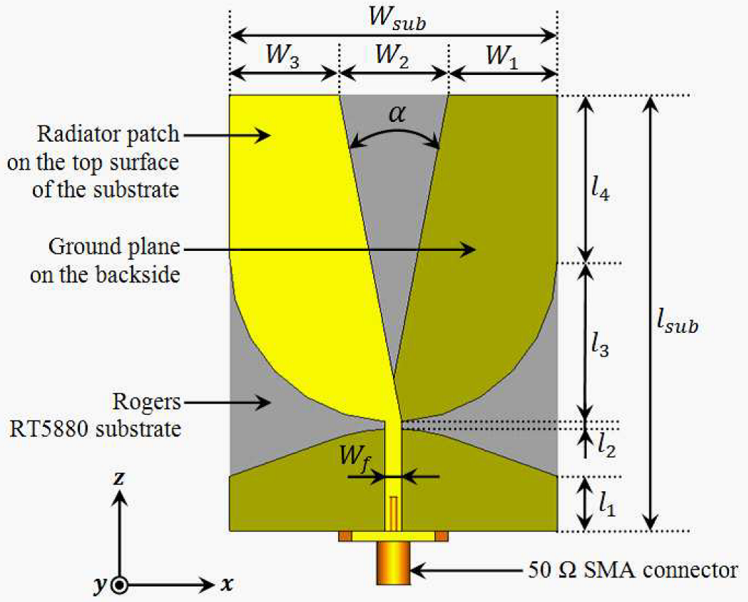
Figure2: Geometry of Vivaldi Antenna from [4]
The antenna final design dimensions are summarized in the table below:
| Wsub | 48mm |
| W1 | 16mm |
| W2 | 16mm |
| W3 | 16mm |
| Wf | 2.4mm |
| lsub | 64mm |
| l3 | 24mm |
| l4 | 24mm |
Figure3: Proposed Vilvaldi Antenna Dimensions
As it can be seen below, the ground plane surface was greatly reduced in my design contrary to the design discussed in [4] have. I found out that modifying the ground plane substantially improved the performance of the antenna: gain, bandwidth and efficiency.
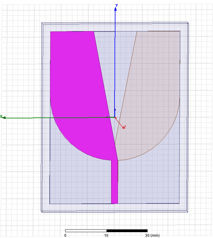
Figure4: Designed Vivaldi Antenna as per Dimension Above
Simulation results for Antipodal Vivaldi antenna
The antenna performance with modified ground plane, Figure4, turns out to give better performance than the antenna without modified ground plane Figure2. The antenna with the ground plane unmodified showed a radiation pattern with maximum radiation beam pointing slightly towards the ground plane.This occurs due having an antenna geometry that is not symmetric. However, the second design with the ground plane modified resulted in an antenna with asymmetric geometry, and therefore resulted in an improved radiation pattern that is of an end fire antenna.
The figures below show the simulation results collected for the modified Antipodal Vivaldi antenna:
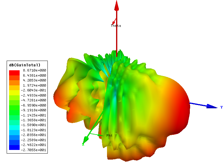
Figure5. 3D radiation pattern at 28 GHz
The figure above show that that the antenna has a maximum radiation in the direction of X axis, which is what we expected,as the antenna is supposed to be an End-Fire antenna. Also, on the same plots we see that the maximum gain of the antenna is 8.7 dBi, which is slightly above the gain I was aiming for.
The S11 parameters plot below allows us to conclude that this antenna design is a wide band antenna. It can operate for any high frequency that falls between 20GHz to 40GHz, which meet our requirements.
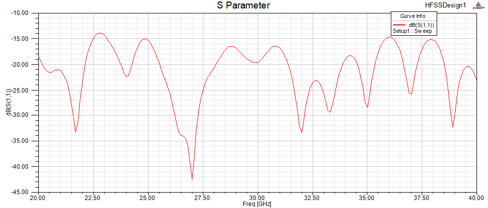
Figure6. S11 Parameters
The plot below shows that the proposed design exhibit a higher radiation efficiency, which means that this antenna is almost lossless: most of the power can be transmitted with almost no losses.
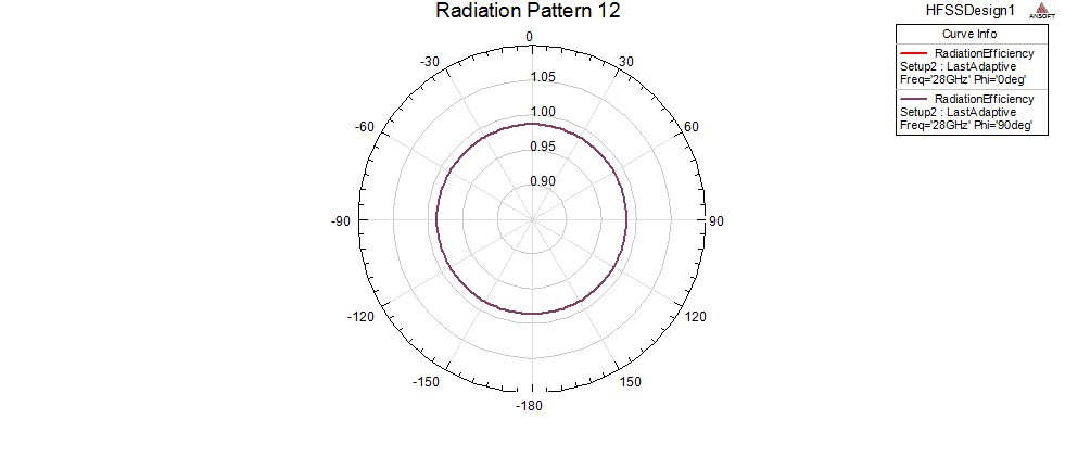
Figure7. Radiation efficiency at 28GHz
The figure below shows the current distribution on the top conducting surface. The current follows along the edges of the curve. The current density is higher at start of the curve close to the feed line.
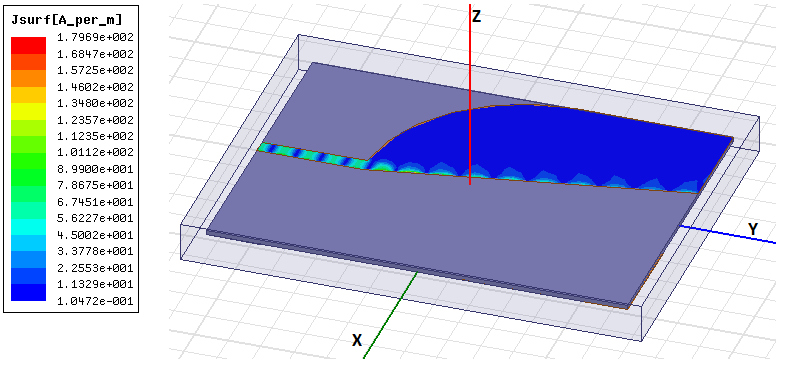
Figure8. Current Distribution at 28GHz
The figure below shows the 3D radiation pattern at 28 GHz, it verifies that the antenna is an end-fire, as the maximum radiation is in parallel to the curves and perpendicular to the top edge of the antenna.
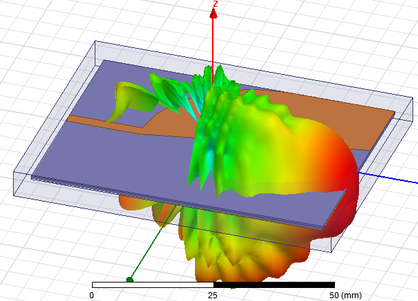
Figure9.3D radiation pattern at 28GHz
Implementation
The antenna was build according to the following steps:
- Step1: The antenna was printed with a 1:1 scale on a toner transfer paper
- Step2:The printed antenna was transferred to the copper sheet using a heated iron.The image below shows the printed antenna on copper sheet.
- Step3: we used the green TRF foil to seal the printed antenna on the copper sheet
- Step 4:used an inching solution, Ferric Chloride, was used to itch the antenna. The images below illustrate all the steps.
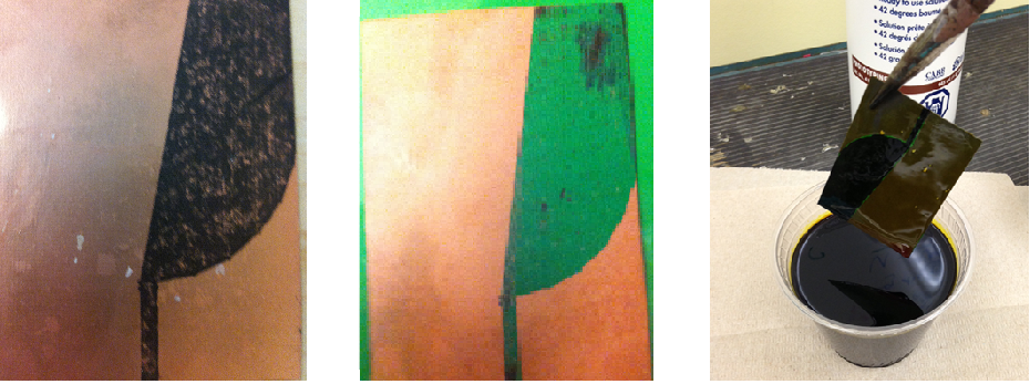
Figure10: After Ink Toner Transfer Figure11: After TRF Foil Figure12: Itching solution
- Step 5: in this last step, a 50 Ohms, 3.5 mm SMA was soldered to the antenna as shown below:
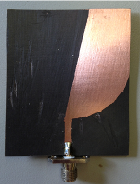
Figure13: Final Antenna Prototype
Testing and Validation
To verify the performance of our design, and the simulations results, the antipodal Vivaldi Antenna we designed was tested in the Radio Frequency lab using the vector Network Analyzer: Agilent E8361A10MHz-67GHz.
Below are the steps and guideline I followed for taking our test measurement:
- Use of HFFS to simulate results, prior to building the prototype
- Use the VNA to check the S parameter, after the first antenna element is built.
- Use the Anechoic chamber to measure the efficiency, and gain.
- Use of Anechoic chamber to measure the efficiency, cross polarization, and gain for the entire Antenna array, 6 antenna elements
- Performed a field test of the antenna, in free space.
Results
Using the VNA after doing the right calibration for the SMA and coaxial cables, I measured the S11 parameters of the antenna. The figure below shows the results obtained. However, we could not obtain the correct measurements for the entire spectrum from 20 GHz to 40 GHz, as we used an SMA that support measurements for frequencies that are up to 26.5 GHz only. But from the measurements taken below, we can see that the S11 parameters taken for frequencies from 18GHz to27GHz matches the simulation results. This is apparently, a good sign that the simulation results are very accurate, considering the fact that we used very simple methods to build the antenna prototype. Had we used an itching machine with precise cutting capabilities and an SMA that can support measurement for frequencies up to 40 GHz, we could have obtained S11 parameters results identical to the simulation results.

Figure14: S11 Parameters Taken from the VNA
Conclusions
An ultra wideband Vivaldi antenna for applications in Local Multipoint Communications Systems, LMCS, bands was designed and simulated. The antenna scans for direction of the transmitted signal with the maximum energy via beam-forming. The frequency bandwidth of the designed antenna extends from 20GHz to 40GHz with a higher efficiency that is more than 90%, and a peak gain that is around 9 dBi.The collected simulated and measured results proved that the designed antenna met the design requirements.
If you find any of the projects posted here helpful to you while working on similar projects, or you learned something from any of the topics discussed, please do not hesitate to make a donation, whatever amount you can afford, just as a gesture of appreciation and to keep this website alive and progressing so that its benefits extends to many younger engineers and students around the globe
References
[1] Gibson, P. J. “The Vivaldi Aerial.” In Microwave Conference, 1979, 9th European, pp. 101-105. IEEE, 1979
[2]Y. Yang, Y. Wang, and A. E. Fathy, “Design of Compact Vivaldi Antenna arrays for UWB See Through Wall Applications,” Progress In Electromagnetics Research,PIER 82, 401–418, 2008
[3]Guangyou FANG and Motoyuki SATO, “Optimization of Vivaldi Antenna for Demining by GPR,” Center for Northeast Asian Studies, Tohoku University, Kawauchi,Sendai, 980-8576, Japan
[4]Alhawari, Adam Reda Hasan, Alyani Ismail, Mohd Adzir Mahdi, and Raja Syamsul Azmir Raja Abdullah, “Antipodal Vivaldi Antenna Performance Booster Exploiting snug-in Negative index Metamaterial,” Progress InElectromagnetics Research C 27 (2012): 265-279


Great work Farid!
LikeLike
Glad to hear 🙂
LikeLike
Interesting work ! – – check out some of my antennas here :
https://grabcad.com/steven.minichiello-1/models
LikeLike