
This Tutorial is related to the previous post UART Serial Interface.
In this example, I demo the use of an XBee S1 module in transmitting a battery voltage remotely. More info about XBee module can be found at this link:
The XBee S1 uses a uart interface for communication. For more info about how UART works, see the previous link: UART Serial Interface.
Wires Connection
I soldered TX:pin2 and RX: pin 3 of the module, respectively, to RX:PA9 and TX: PA 10 of the STM32F0 Discovery Dev Board.
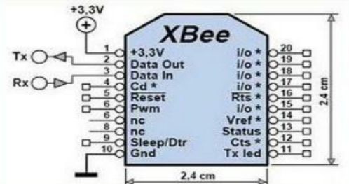
Figure1: Xbee S1 Module Pinout
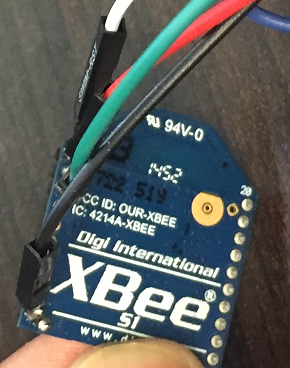
Figure2: XBee S1 Module I used in the Demo
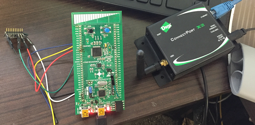
Figure3: Demo Setup
Data Flow
Data is sent from the MCU via UART to XBee Module and is sent wirelessly to XBee PRO gateway which send received data to my laptop via a serial terminal. However, before this can happen both the transmitting XBee module and Connect Port X2, receiver, need to be configured correctly.
Configuration Using XTU
I set the baud rate for both modules to 9600b/s, no parity and one stop bit. API is set to Disabled.
S1 Module: CH:C, ID:555, DH:0, DL:2, MY:1; and for XBee Pro gateway: CH:C, ID:555, DH:0, DL:2, MY:2
STM32F0 ADC is used for measuring the battery voltage, and below is how it is configured. In this case, I did not use an interrupt, but instead it was configured so that I read measurements in a polling approach. Below is the configuration:
/**
* @brief ADC MSP Initialization
* This function configures the hardware resources used in this example:
* - Peripheral's clock enable
* - Peripheral's GPIO Configuration
* @param hadc: ADC handle pointer
* @retval None
*/
void HAL_ADC_MspInit(ADC_HandleTypeDef *hadc)
{
GPIO_InitTypeDef GPIO_InitStruct;

/*1- Enable peripherals and GPIO Clocks */
/* ADC Periph clock enable */
ADCx_CLK_ENABLE();     //__HAL_RCC_ADC1_CLK_ENABLE()

/* Enable GPIO clock */
ADCx_CHANNEL_GPIO_CLK_ENABLE(); //__HAL_RCC_GPIOC_CLK_ENABLE()

/*2- Configure peripheral GPIO*/
/* ADC Channel GPIO pin configuration */
GPIO_InitStruct.Pin = ADCx_CHANNEL_PIN; //GPIO_PIN_0
GPIO_InitStruct.Mode = GPIO_MODE_ANALOG;
GPIO_InitStruct.Pull = GPIO_NOPULL;
HAL_GPIO_Init(ADCx_CHANNEL_GPIO_PORT, &GPIO_InitStruct); //GPIOC
}
void ADC_Init(void)
{
/*Configure the ADC peripheral */
AdcHandle.Instance = ADCx;   //ADC1

if (HAL_ADC_DeInit(&AdcHandle) != HAL_OK)
{
  /* ADC de-initialization Error */
  Error_Handler();
}
AdcHandle.Init.ClockPrescaler = ADC_CLOCK_SYNC_PCLK_DIV4;
AdcHandle.Init.Resolution = ADC_RESOLUTION_12B;
AdcHandle.Init.DataAlign = ADC_DATAALIGN_RIGHT;
AdcHandle.Init.ScanConvMode = ENABLE;
AdcHandle.Init.EOCSelection = ADC_EOC_SINGLE_CONV;
AdcHandle.Init.LowPowerAutoWait = DISABLE;
AdcHandle.Init.LowPowerAutoPowerOff = DISABLE;
AdcHandle.Init.ContinuousConvMode = ENABLE; /* Continuous mode disabled to have only 1 conversion at each conversion trig */
AdcHandle.Init.DiscontinuousConvMode = DISABLE; /* Parameter discarded because sequencer is disabled */
AdcHandle.Init.ExternalTrigConv = ADC_SOFTWARE_START; /* Software start to trig the 1st conversion manually, without external event */
AdcHandle.Init.ExternalTrigConvEdge = ADC_EXTERNALTRIGCONVEDGE_NONE;
AdcHandle.Init.DMAContinuousRequests = DISABLE;
AdcHandle.Init.Overrun = ADC_OVR_DATA_OVERWRITTEN;

if (HAL_ADC_Init(&AdcHandle) != HAL_OK)
{
/* ADC initialization Error */
Error_Handler();
}

/*2- Configure ADC regular channel*/
sConfig.Channel = ADC_CHANNEL_10;
sConfig.Rank = 1;
sConfig.SamplingTime = ADC_SAMPLETIME_28CYCLES_5;

if (HAL_ADC_ConfigChannel(&AdcHandle, &sConfig) != HAL_OK)
{
 /* Channel Configuration Error */
  Error_Handler();
}
/* -3- Start the conversion process*/
if (HAL_ADC_Start(&AdcHandle) != HAL_OK)
{
   /* Start Conversation Error */
   Error_Handler();
}
}
The data is sent at an interval of 1 second, and it was displayed using the serial terminal of the XTU. The battery voltage ranges from 1.48V to 1.55V
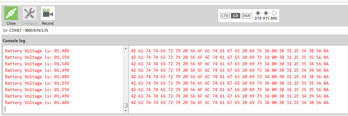 Figure4: Sensed Battery Data received
Figure5: XBee Demo Video
Conclusion
This is just a simple example that shows one of the applications of XBee modules. Certainly I can be used in a wide range of applications such as remote sensing and remote data monitoring. Currently, I am exploring the uses of these modules in Modbus and CANopen data communication.
If you like this posting or have any questions, please drop us a feedback in the comments section!
