
Note: This tutorial is related to the Xbee Demo I am discussing later, after this post.
This page explains the implementation of Universal Asynchronous Receiver and Transmitter, UART, on STM32F0 MCU. More info about this serial protocol can be found in this tutorial.
In this project, I used an STM32F0 Discovery development board to send a data string to my laptop and display it on Tera Term serial console.
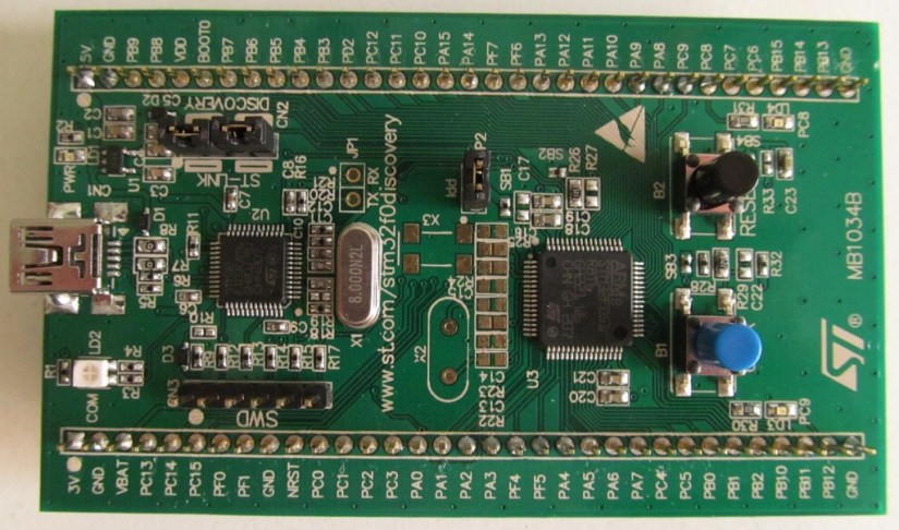 Figure1: STM32F0 Discovery Board
The Board has STM32F072RB MCU which comes with 4 UART peripherals. But the board has only access to UART1, which has the following IOs: RX is PA10 and TX is PA9. Since this board has a VCC voltage of only 3V, it is needed to use an RS232 to TTL converter to level shift the 3V voltage to 15V when data is sent to the PC and shift the voltage from 15V to 3V when data is received by the MCU. In this example, I used this serial adapter board below, that comes with a Maxim Chip converter MAX3232:
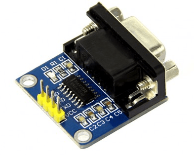 Figure2: RS232 RS232 to TTL Converter
Pins Connection
You need to connect RX( pin PA10) of the MCU to TX pin of the adapter and connect TX(PA9) of the MCU to RX of the adapter, then connect VCC of the MCU to VCC of the adapter and GND pin of the MCU to GND of the adapter.
Firmware Configuration
The UART peripheral is configured to run at 9600 b/s, with no parity and one 1 stop bit. Below is how it is done:
/* Put the USART peripheral in the Asynchronous mode (UART Mode) */
/* UART configured as follows:
- Word Length = 8 Bits
- Stop Bit = One Stop bit
- Parity = None
- BaudRate = 9600 baud
- Hardware flow control disabled (RTS and CTS signals) */
void UART_Init(void)
{
  UartHandle.Instance = USARTx; // USART2 is used
  UartHandle.Init.BaudRate = 9600;
  UartHandle.Init.WordLength = UART_WORDLENGTH_8B;
  UartHandle.Init.StopBits = UART_STOPBITS_1;
  UartHandle.Init.Parity = UART_PARITY_NONE;
  UartHandle.Init.HwFlowCtl = UART_HWCONTROL_NONE;
  UartHandle.Init.Mode = UART_MODE_TX_RX;
  UartHandle.AdvancedInit.AdvFeatureInit = UART_ADVFEATURE_NO_INIT;
  if(HAL_UART_DeInit(&UartHandle) != HAL_OK)
  {
    Error_Handler();
  }
 if(HAL_UART_Init(&UartHandle) != HAL_OK)
 {
  Error_Handler();
 }
}
The IOs TX and RX are configured as below:
/**
* @brief UART MSP Initialization
* This function configures the hardware resources used in this example:
* - Peripheral's clock enable
* - Peripheral's GPIO Configuration
* @param huart: UART handle pointer
* @retval None
*/
void HAL_UART_MspInit(UART_HandleTypeDef *huart)
{
   GPIO_InitTypeDef GPIO_InitStruct;
   /*1- Enable peripherals and GPIO Clocks */
   /* Enable GPIO TX/RX clock */
   USARTx_TX_GPIO_CLK_ENABLE();
   USARTx_RX_GPIO_CLK_ENABLE();
   /* Enable USARTx clock */
   USARTx_CLK_ENABLE();

   /*2- Configure peripheral GPIO */
   /* UART TX GPIO pin configuration */
   GPIO_InitStruct.Pin = USARTx_TX_PIN;
   GPIO_InitStruct.Mode = GPIO_MODE_AF_PP;
   GPIO_InitStruct.Pull = GPIO_PULLUP;
   GPIO_InitStruct.Speed = GPIO_SPEED_FREQ_HIGH;
   GPIO_InitStruct.Alternate = USARTx_TX_AF; // Pin PA9
   HAL_GPIO_Init(USARTx_TX_GPIO_PORT, &GPIO_InitStruct);

   /* UART RX GPIO pin configuration */
   GPIO_InitStruct.Pin = USARTx_RX_PIN;
   GPIO_InitStruct.Alternate = USARTx_RX_AF; //Pin PA10
   HAL_GPIO_Init(USARTx_RX_GPIO_PORT, &GPIO_InitStruct);
}
Below is how UART transmit function is called inside main.c file. A string is sent one every second to Tera Term console.
/* TX Buffer */
char aTxBuffer[] = "Xbee S1 Test.. for Wireless Temperature Sensors!!\n";

int main()
{
   HAL_Init();
   /* Configure LED3, LED4, LED5 and LED6 */
   LEDs_Init()
   /* Initialise ADC */
   ADC_Init();
   /* Configure the system clock to 168 Mhz */
   SystemClock_Config();
   /*Configure the UART peripheral */
   UART_Init();
   while(1)
   {
     HAL_UART_Transmit(&UartHandle, (uint8_t*)aTxBuffer, sizeof(aTxBuffer), 5000); //TXBUFFERSIZE
     HAL_Delay(1000);
   }
}
Below is a the data received on Tera Term console. To view the data make sure that the serial port on Tera Term is configured correctly. From Setup, select serial port and set the correct baud rate, parity, and stop bit to values equal to what you defined in your firmware. Also make sure that Local Echo is checked( you can access this from Setup->Terminal).
 Figure3: Tera Term Data Display
Conclusion
This was a simple introduction to UART interface using STM32 Cortex M0 MCU. It does not use any UART interrupts, but I will try to post an example that uses interrupts in the near future.
Again, if you like this page or have any questions, feel free to drop us a feedback in the comments section.
