

In this page, we will learn about I2C serial protocol and how to implement it on an STM32F4 MCU. As an example, we are using a 1Mbit M24M02 EEPROM to demonstrate how I2C protocol works and how it should be configured properly. In the meantime, I want to mention that I used this nonvolatile memory, M24M02, for implementing a real time data logging system via I2C. More info about M24M02 EEPROM can be found at the datasheet.
First, let’s talk a bit about I2C as a protocol. I2C is a two wire serial communication protocol developed by Philips. It is a communication between a master and a slave. There can be a total of 127 slaves on the same I2C bus, and each slave have its unique address. Initial I2C speed was defined at 100 kHz, and later it became 400 kHz. There are other speeds, for example: High speed mode has 3.4 MHz clock frequency and ultra-fast mode has a clock frequency of 5MHz.
I2C Interface
I2C uses two wires: SCL (serial clock) and SDA (serial data). Both need to be pulled up with a resistor to +Vdd. For this EEPROM, I used a 2K resistors.
I2C Addresses
Each I2C slave device has a 7-bit address that needs to be unique on the bus. Some devices have fixed I2C address while others have few address lines which determine lower bits of the I2C address. This makes it very easy to have all I2C devices on the bus with unique I2C address. There are also devices which have 10-bit address as allowed by the specification[1].
Firmware Implementation
Source code is on my repository on Github: I2C.
The source code section below shows the I2C configuration. The clock has been set to 400KHz, and we used 7 bits addressing mode.
/* Configure the I2C peripheral */ void I2C_Config(void)
{
I2cHandle.Instance = I2C1;
I2cHandle.Init.AddressingMode = I2C_ADDRESSINGMODE_7BIT;
I2cHandle.Init.ClockSpeed = 400000;
I2cHandle.Init.DualAddressMode = I2C_DUALADDRESS_DISABLED;
I2cHandle.Init.DutyCycle = I2C_DUTYCYCLE_16_9;
I2cHandle.Init.GeneralCallMode = I2C_GENERALCALL_DISABLED;
I2cHandle.Init.NoStretchMode = I2C_NOSTRETCH_DISABLED;
I2cHandle.Init.OwnAddress1 = 0x0A;
I2cHandle.Init.OwnAddress2 = 0xFE;
if(HAL_I2C_Init(&I2cHandle) != HAL_OK)
{
/* Initialization Error */
I2c_Error_Handler();
}
}
EEPROM Write
The section below shows how to write a block of data to the EEPROM. In this demo, we are writing the following hex values: 0x0C, 0x0D, and 0x0E. The slave address as per the data sheet is: 0x0A.
voidWrite_EEPROM(void)
{
  I2CMemAddress=0;  /*write enable */

  HAL_GPIO_WritePin(GPIOA, EEPROM_WR_EN, GPIO_PIN_RESET);
  /*As per data sheet: The 256 Kbytes (2 Mb) are addressed with 18 address bits,
  the 16 lower address bits being defined by the two address bytes and the most
  significant address bits (A17, A16) being included in the Device Select code.*/

  /*Parameters: I2C handle,DevAddress,MemAddress,MemAddSize,data buffer pointer,Size,Timeout */
  HAL_I2C_Mem_Write(&I2cHandle, I2C_DevSelectAddress_WR,I2CMemAddress, 2,WrBuffer,3,100);
  /* DISABLE writing to EEPROM */
  HAL_GPIO_WritePin(GPIOA, EEPROM_WR_EN, GPIO_PIN_SET);
}
Initially, we send the slave address byte, followed by the block of data we need to write as per the details in the datasheet.
The slave address bye is made of 7 bits for the device address, and the 8th bit is low. When this 8th bit is low it indicate a write command and when it’s high it indicates a read command. Note also here that after every byte we transmit over the bus we receive an ACK from the addressed slave.
 Figure 1. Write mode sequences with WC = 0 (data write enabled)[2]
Below are the I2C signals: yellow is clock, blue is data line, and purple is write enable. as per data sheet, this line needs to be low for writing and pulled up high for write protection.
 Figure2. Write data command packet
EEPROM Read
The function below is called every time a read of a certain address location is needed.
void Read_EEPROM(void)
{
  I2CMemAddress=0;
  //Parameters: I2C handle,DevAddress,MemAddress,MemAddSize,data buffer pointer,Size,Timeout
  HAL_I2C_Mem_Read(&I2cHandle,I2C_DevSelectAddress_RD, I2CMemAddress, 2, RdBuffer, 3, 100);
  HAL_Delay(5);
}
As per the data sheet, we send a write command: 7 bits for slave address and 8th bit is low, indicating a write command. Then we receive an ACK from the slave, then we send a 16 bits memory address for the EEPROM, and later we send a read command: 7 bits for the slave address and 8th bit high, indicating a read command. More details are in the datasheet. Note that after each byte we send, we receive an ACK from the slave:EEPROM.
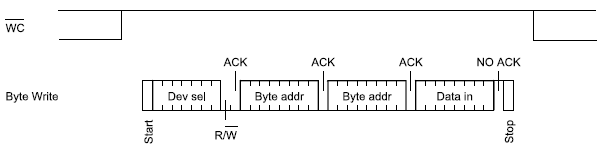 Figure 3. Write mode sequences with WC = 1 (data write inhibited)[2]
Below are the I2C signals: yellow is clock and blue is data line.
 Figure4. Read data command packet[2]
If you find any of the projects posted here helpful to you while working on similar projects, or you learned something from any of the topics discussed, please do not hesitate to make a donation, whatever amount you can afford, just as a gesture of appreciation and to keep this website alive and progressing so that its benefits extends to many younger engineers and students around the globe
References
[1] I2C Info – I2C Bus, Interface and Protocol. Retrieved from http://i2c.info/
[2] 2-Mbit serial I²C bus EEPROM. Retrieved from https://www.st.com/resource/en/datasheet/m24m02-dr.pdf
