
In this post, I will discuss the implementation of a linear speed controller for a stepper motor. The algorithm used in generating this linear speed profile is taken from this article: “Generate stepper-motor speed profiles in real time” posted by David Austin [1].
The firmware was on implemented on a an ARM7 LPC2378. The development board MCB2370 was used to validate and test the code.

Firmware Implementation
First, we calculate the initial delay constant C0, as indicated in equation 7 of the paper[1]: C0=clock frequency*sqrt(2*motor_step_angle/angular_accel).
angular_accel= 4 (rad/sec^2); motor_step_angle= 0.0019625 (rad), and clock frequency= 1200000 Hz.
void Calculate_C0()
{
 /*C0 equation: C0=frequency*sqrt(2*motor_step_angle/angular_accel)*/
 step=0;
 temp0=2*motor_step_angle;
 temp0=temp0/angular_accel;
 temp0=fastsqrt(temp0);
 temp0=temp0*frequency;
}
Then, we calculate time constant C1 using equation 12 of [1]. This time constant will be used to generate the first pulse delay. Cn equation: Cn= (Cn-1)-(2*Cn-1/(4*step+1)).
/*C1= (C0)-(2*C0/(4*step+1))*/
step++;
denom=(step<<2)+1;
temp1=(temp0+temp0)/denom;
temp0=temp0- temp1;

/* normalization so that delays are obtained in Microseconds */
temp3=ceil(temp0/12);
delay_constant=temp3;
In the second step, we set up a timer interrupt for calculating the time delay between pulses. I should mention here that the motor speed increases as the time delay gets shorter between pulses, and also speed slows down as time delay between pulses increases. The timer interrupt is set up as below.
Once the first time delay constant is calculated, it is loaded into the timer register T0MR0. The calculation for the next time delay is being processed while the timer is counting up to the value of the previous time delay.
void SetupTimerInterrupt(void )
{ /* setup the timer interrupt */
  T0MCR = 3;                          /* Interrupt and Reset on MR0 */
  VICVectAddr4 = (unsigned long ) T0_IRQHandler; /* Set Interrupt Vector */
  VICVectCntl4 = 15                   /* use it for Timer0 Interrupt */
  VICIntEnable = (1 << 4);
  T0TCR = 1;                          /* Timer0 Enable */
  T0MR0 = delay_constant;
}
We define our timer interrupt as below:
__irq void T0_IRQHandler (void)
{
int i;
j++;    //keep track of number of steps.
for(i=0; i<120; i++) { ; } //this controls the width of the pulse

if (j==4100)      //total number of steps
{
 T0TCR = 0;        /* Timer0 Enable */
 next_state=0x4;   //Exit state
}
else
{
 T0MR0 =delay_constant;
}
T0IR = 1;         /* Clear interrupt flag */
VICVectAddr = 0;
flag=1;           /* this flag signals to main loop to calculate the subsequent time delay  */
}
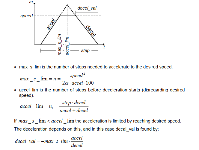
The total number of steps the motor has to travel is 4200. To complete these steps and meet the travel time requirements, the motor goes through three stages: Speed up, Cruise, and Slow down. The motor needs to speed up to reach the desired speed and once it reaches such a speed, it stay at that speed before it starts slowing down. The equations below are used to define the points at which to start slowing down.
int main (void)
{
 LED_Init(); /* LED Initialization */
 Calculate_C0();
/*Cn equation: Cn= (Cn-1)-(2*Cn-1/(4*step+1))*/
/*C1= (C0)-(2*C0/(4*step+1))*/
 step++;
 denom=(step<<2)+1;
 temp1=(temp0+temp0)/denom;
 temp0=temp0- temp1;

 /* normalization so that delays are obtained in Microseconds */
 temp3=ceil(temp0/12);
 delay_constant=temp3;
 flag=1;

 SetupTimerInterrupt();
 next_state=0x1;

while(1)
{
  if(flag)
  {
   flag=0;
   switch(next_state)
  {
    case SPEED_UP:
    step++;
    if(step==1200)
    {
      next_state=0x2;
    }
    denom=(step<<2)+1;
    temp1=(temp0+temp0)/denom;
    temp0=temp0- temp1;

    /* normalization so that delays are obtained in Microseconds */
    temp3=ceil(temp0/12);
    delay_constant=temp3;
    break;

    case CRUISE:
    step++;
    if(step==3001)
    {
     delay_constant=temp3;
     next_state=0x3;
    }
    break;
   case SPEED_DOWN:
   /*Cn equation: Cn= (Cn-1)-(2*Cn-1/4*(step-total_steps)+1)*/
   denom= total_steps-step;
   denom=(denom<<2)-1;
   temp1=(temp0+temp0)/denom;
   temp0=temp0+temp1;

   /* normalization so that delays are obtained in Microseconds */
   temp3=ceil(temp0/12);
   delay_constant=temp3;

   step++;
   if(step==4199)
   {
     next_state=0x4;
   }
   break;
   case IDLE:
   printf("Idle\n" );
   break;
   default :
   printf("exit\n" );
   }
  }
 }
}
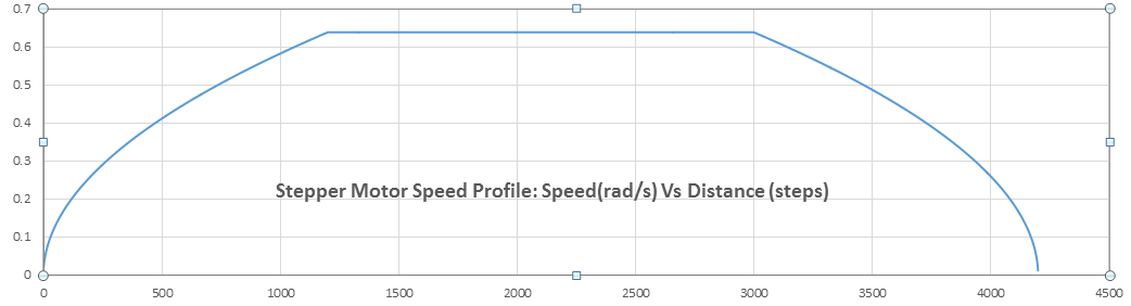
Motor Speed Profile
The plot below shows the generated speed profile using the implemented algorithm above. It can clearly be seen that the angular speed is linear especially after a few steps from the start of the motor.
Below is a demo video for a stepper motor speed controller I developed for a printer auto cleanup prototype. I implemented the same algorithm discussed above but this time on a Xilinix FPGA, Spartan6. The moving system also carries a diaphram pump that you hear actuated only at certain sections of the rails.
Firmware Download
The firmware can be downloaded from the link below:
https://github.com/fma23/Stepper-motor-linear-speed-controller/tree/master
If you like this posting or have any questions, please drop us a feedback in the comments section!
References
[1] David Austin, “Generate stepper-motor speed profiles in real time.” Retrieved from: https://www.embedded.com/design/mcus-processors-and-socs/4006438/Generate-stepper-motor-speed-profiles-in-real-time
[2] “Linear speed control of stepper motor.” Retrieved from: http://ww1.microchip.com/downloads/en/appnotes/doc8017.pdf
