
Author: Farid M, https://embeddeddesign.org/
In this new post, I will show you how to convert a 6th-order IIR filter into
three biquad sections, and then implement the resulting filter using VHDL.
The filter we’re designing is a 75 kHz low-pass filter, as discussed in the previous post. In the section below I will use Matlab to convert Direct form II equation we used in the last project to create a three biquads which we use cascaded them in series to realize our IIR filter.
🛠️ Converting a Direct Form II IIR Filter to Biquads Using MATLAB
The first question to ask is why we need to convert a high order direct form II into second order sections or biquads? There are a lot of reasons why we need to that, and one of the reasons is accuracy improvement and stability optimization.
We have seen before in my last post how distorted the filtered noisy 10KHz signal turned out to be after it went through the filter.
Below is a lit of reasons why a high order IIR fitter needs to be broken down into a series of second order filters or Biquads:
1. Improved Numerical Stability
-
Problem: High-order filters in Direct Form II suffer from numerical instability due to rounding errors and finite word length effects.
-
Solution: Splitting the filter into second-order sections (biquads) reduces the chance of error accumulation and increases stability.
2. Reduced Quantization Error
- In fixed-point implementations (like in VHDL), coefficient quantization and arithmetic rounding can severely distort the filter’s behavior.
- Biquads localize error effects within each section, preventing them from propagating across the entire filter.
3. Easier to Manage Scaling
-
You can apply gain scaling between biquads to prevent overflow or underflow, which is much harder in a single high-order structure.
4. Better Performance in Hardware
- Biquads allow parallel or pipelined implementation in hardware, improving throughput and latency.
- Simplifies resource allocation in FPGA (like DSP blocks or multipliers).
5. Modular Design
- Biquads are reusable and testable submodules.
- Easier to debug and validate each section individually.
- To implement a high-order IIR filter (such as a 6th-order design) in hardware, it’s common to break it down into smaller second-order sections (biquads) for improved numerical stability and easier VHDL implementation.
🔢 MATLAB COMMAND
MATLAB provides a built-in function called tf2sos that converts a filter defined by its numerator and denominator coefficients into a cascade of biquads (second-order sections). In the Filter Design tool, once you generate the coefficients of your IIR filter in Direct Form II, go to file and select export.
% Convert to Second-Order Sections (SOS)

tf2sos(Num , Num);
✔ Each biquad is represented as:
H(z) = (b₀ + b₁·z⁻¹ + b₂·z⁻²) / (1 + a₁·z⁻¹ + a₂·z⁻²)
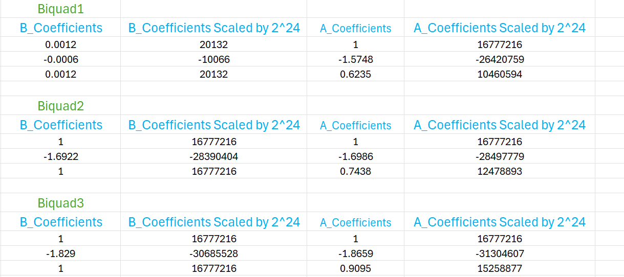
The following image shows the b and a coefficients for each of the three biquads of the 6th-order IIR filter, along with their fixed-point scaled versions (multiplied by 224) for VHDL implementation. The non scaled numbers are the ones generated by Matlab.
VHDL IIR Filter Implementation
Three instantiation were created for each Biquad: Biquad1, BiQuad2, and Biquad3. These biquad instantiations were cascaded: having the very first signal input processed by Biquad1 and recovering the final IIR output from Biqud3. The clock frequency of the filter was 100MHz, and all Biquads used valid input signals which goes high for one clock cycle whenever there is a valid input.
The system clock 100MHz was also used to generated the sampling pulse for valid_in signal. The IIR filter was designed to receive a pulse at a frequency of 1.56MHz.
Below is a copy of the three Biquad instantiations:
IIR_BIQUAD1: Cascaded_ChbyChevII_Fc37K5_Fp100K_Astop60
PORT MAP (
    clk                      => clk,
    reset                    => reset,
    x_in                     => BiQuad1_x_in_Sig,
    iir_out                  => iir_out_Biquad1,
    BiQuad_sample_valid_in   => sample_valid_in_sig,
    BiQuad_sample_valid_out  => BiQuad1_sample_valid_out_Sig,
    b0                       => Biquad1_B_Coefficients(0),
    b1                       => Biquad1_B_Coefficients(1),
    b2                       => Biquad1_B_Coefficients(2),
    a1                       => Biquad1_A_Coefficients(1),
    a2                       => Biquad1_A_Coefficients(2),
    busy                     => Busy_Biquad1_Sig
);
IIR_BIQUAD2: Cascaded_ChbyChevII_Fc37K5_Fp100K_Astop60
PORT MAP (
    clk                      => clk,
    reset                    => reset,
    x_in                     => iir_out_Biquad1,
    iir_out                  => iir_out_Biquad2,
    BiQuad_sample_valid_in   => BiQuad1_sample_valid_out_Sig,
    BiQuad_sample_valid_out  => BiQuad2_sample_valid_out_Sig,
    b0                       => Biquad2_B_Coefficients(0),
    b1                       => Biquad2_B_Coefficients(1),
    b2                       => Biquad2_B_Coefficients(2),
    a1                       => Biquad2_A_Coefficients(1),
    a2                       => Biquad2_A_Coefficients(2),
    busy                     => Busy_Biquad2_Sig
);
IIR_BIQUAD3: Cascaded_ChbyChevII_Fc37K5_Fp100K_Astop60
PORT MAP (
    clk                      => clk,
    reset                    => reset,
    x_in                     => iir_out_Biquad2,
    iir_out                  => iir_out_Biquad3,
    BiQuad_sample_valid_in   => BiQuad2_sample_valid_out_Sig,
    BiQuad_sample_valid_out  => BiQuad3_sample_valid_out_Sig,
    b0                       => Biquad3_B_Coefficients(0),
    b1                       => Biquad3_B_Coefficients(1),
    b2                       => Biquad3_B_Coefficients(2),
    a1                       => Biquad3_A_Coefficients(1),
    a2                       => Biquad3_A_Coefficients(2),
    busy                     => Busy_Biquad3_Sig
);
IIR_FilterOut <= iir_out_Biquad3;
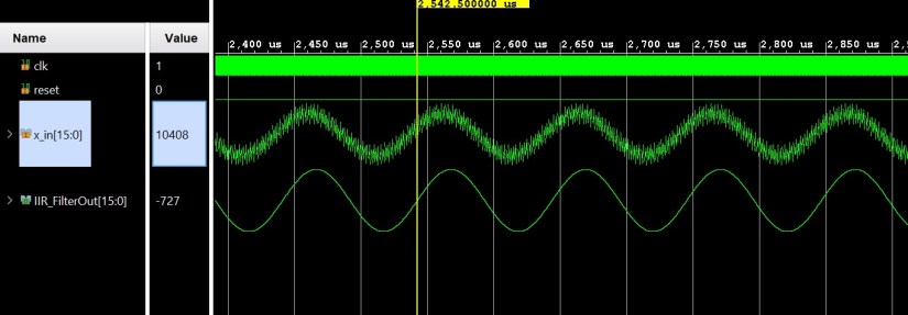
IIR Filter Simulation Results
Conclusion and Future Improvement
We demonstrated that the accuracy of the output IIR filter can be improved by reconstructing the IIR filter with cascaded second order filters. Matlab was used to generated the second order filters or the Biquads. In our case, the filter we designed was a sixth order filter therefore we needed three cascaded Biquads.
The VHDL code was written in a way that makes it modular and easy to expand to other higher order filters. In our case, we have created three Instantiations: one IIR filter instantiation per Biquad. Thus for an an 8th or 7th order IIR filter we can create a fourth instantiation. In addition to all this, the VHDL code can work for any other filter, the user needs only change the coefficient a and b values for the Biquads. The complete code is available upon request.
Future work: The developed code would not run at higher frequency. I could ran only up to 200MHz frequency. Thus if you require to have your IIR filter run at 400 MHz, you will need to use DSP slices in your code, and this is something I would like to demonstrate in my next posting. Stay tuned!
Cascaded IIR Filter VHDL Complete Source Code
If anyone is interested in the complete code, drop me an email or message me in the comments section.
Farid M
