
In this tutorial, I will show you how to use the power voltage detector interrupt with STM32F4 MCU. It occurred to me one time that I had to save a critical data that was continuously computed to an EEPROM in case the system loses power, unexpectedly. After a little thinking, I decided to use PVD interrupt to save my data in case the MCU power rails goes below 2.9V.
PVD Configuration
Below is how PVD is configured. The below configuration uses STM HAL library. Initially, you enable the power clock, then you alarm the PVD interrupt and give it a priority. Also you set the level for this interrupt: this is the voltage level at which the interrupt is triggered, in my case I set it to 2.9V.
void PVD_Config(void)
{
/* 1. Enable Power Clock*/
_PWR_CLK_ENABLE();

/*2. Configure the NVIC for PVD */
HAL_NVIC_SetPriority(PVD_IRQn, 0, 0);
HAL_NVIC_EnableIRQ(PVD_IRQn);

/* Configure the PVD Level to */
sConfigPVD.PVDLevel = PWR_PVDLEVEL_3;
sConfigPVD.Mode = PWR_MODE_IT_RISING_FALLING;
HAL_PWR_PVDConfig(&sConfigPVD);

/* Enable the PVD Output */
HAL_PWR_EnablePVD();
}
When the voltage rail powering the MCU goes below 2.9V, the PVD interrupt is triggered causing it to call the IRQ handler below:
/******************************************************************************/
/* STM32F4xx Peripherals Interrupt Handlers */
/* Add here the Interrupt Handler for the used peripheral(s) (PPP), for the */
/* available peripheral interrupt handler's name please refer to the startup */
/* file (startup_stm32f4xx.s). */
/******************************************************************************/
void PVD_IRQHandler(void)
{
HAL_PWR_PVD_IRQHandler();
}
The handler above call the function below to handle the PVD interrupt request:
/******************************************************************
This function handles the PWR PVD interrupt request.
This API should be called under the PVD_IRQHandler().
retval None
******************************************************************/
void HAL_PWR_PVD_IRQHandler(void)
{
   /* Check PWR Exti flag */
   if(__HAL_PWR_PVD_EXTI_GET_FLAG() != RESET)
   {
      /* PWR PVD interrupt user callback */
      HAL_PWR_PVDCallback();

      /* Clear PWR Exti pending bit */
      __HAL_PWR_PVD_EXTI_CLEAR_FLAG();
    }
}
Below is the interrupt call back function that is called inside the PVD interrupt service routine.
/****************************************************************
PWR PVD interrupt callback
param none
retval none
****************************************************************/
void HAL_PWR_PVDCallback(void)
{
  Write_EEPROM();
}
The function below is called inside the interrupt, it writes to the M24M02 EEPROM. More details on how to use this EEPROM is on my previous tutorial at this link.
/************************************************************************
This function write to the EEPROM
Return: Mone
************************************************************************/
void Write_EEPROM(void)
{

uint8_t WrBuff[4]={0x34,0x35,0x36,0x37};

I2CMemAddress=0;

/*start writing to the EEPROM */
//RW set low: write enable
HAL_GPIO_WritePin(GPIOA, EEPROM_WR_EN, GPIO_PIN_RESET);

// As per data sheet: The 256 Kbytes (2 Mb) are addressed with 18 address bits,
// the 16 lower address bits being defined by the two address bytes and the most
// significant address bits (A17, A16) being included in the Device Select code.

I2CMemAddress=1;

//Parameters: I2C handle,DevAddress,MemAddress,MemAddSize,data buffer pointer,Size,Timeout
HAL_I2C_Mem_Write(&I2cHandle, I2C_DevSelectAddress_WR,I2CMemAddress, 2,WrBuff,4,100);

HAL_GPIO_WritePin(GPIOA, EEPROM_WR_EN, GPIO_PIN_SET); //DISABLE writing to EEPROM
}
As a demo I am using the function call above to write the following 4 bytes: 0x34,0x35,0x36,0x37.
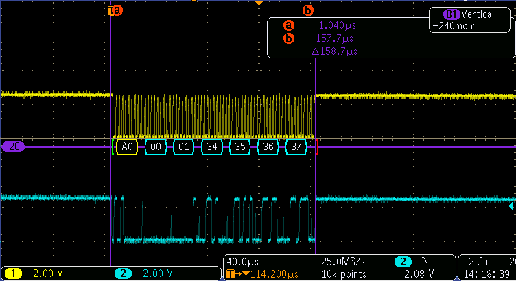 Figure1. Four Bytes Writen to the EEPROM.
As you can see, the scope shows it took around 160 us seconds to write these four bytes. However, in reality, I needed at least 4 ms from the very instance the 3.3V rail dropped to 2.9V and the moment it reached 1.7V. We should not also forget that there is a setup time and hold time requirements for the EEPROM so that data is written correctly.
I hope you enjoyed this tutorial and looking forwards to your feedback!
