
Introduction
In this project, I demonstrate how to design a high-performance Chebyshev Type II Infinite Impulse Response (IIR) digital filter. The first step involves using MATLAB to generate the filter coefficients that meet specific design requirements. This filter type is known for its excellent stopband attenuation while maintaining a smooth, ripple-free passband.
Filter Design Specifications:
- Sampling Frequency (Fs): 1.56 MHz
- Passband Frequency: up to 37.5 kHz
- Stopband Frequency: starting at 100 kHz
- Minimum Stopband Attenuation: 60 dB
Why Chebyshev Type II?
The Chebyshev Type II filter is selected because it offers a sharp transition from the passband to the stopband and provides guaranteed attenuation in the stopband. Unlike Chebyshev Type I filters, which introduce ripple in the passband, Type II filters have a ripple-free passband and allow ripple only in the stopband. This makes them ideal for applications where maintaining signal integrity in the passband is essential.
Comparison with other IIR filters:
- Butterworth filters: Offer a maximally flat passband but have a slower roll-off.
- Elliptic filters: Provide the steepest roll-off but introduce ripple in both passband and stopband.
- Chebyshev Type II filters: Provide a strong stopband attenuation with a clean passband.
Design Approach
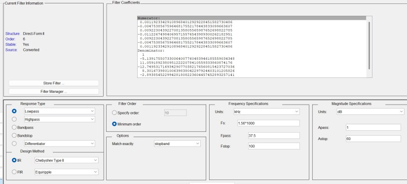
The design process begins with MATLAB’s Filter Design Tool. To launch it, open the MATLAB command console and type: fdatool. A graphical interface will open where you can enter the filter specifications. Once the filter is configured and designed, MATLAB can generate the corresponding coefficients, which can be exported for use in further implementation or analysis.
Below is a screenshot from MATLAB showing the filter settings and the generated coefficients:
Implementation in Fixed-Point
For practical deployment—especially on embedded systems or DSP hardware—we will implement the filter using fixed-point arithmetic. Fixed-point implementation is more resource-efficient compared to floating-point, particularly in terms of memory usage and processing speed. However, it introduces challenges such as limited precision, truncation, and rounding errors.
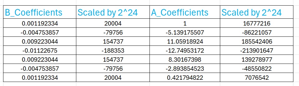
To minimize these errors, it’s essential to scale the filter coefficients to a suitable range before applying them in a fixed-point system. In our design, we chose to scale all coefficients by a factor of 224 (16,777,216). This value provides a good balance between maximizing precision and avoiding overflow during arithmetic operations.
Once the coefficients are scaled, they are rounded and stored as integers. During computation, results must be properly managed (e.g., with bit shifts) to maintain accuracy while staying within the numerical limits of the hardware.
This approach ensures the filter remains both accurate and efficient for real-time applications such as audio processing, communication systems, and other embedded signal processing tasks.
Below is a screen shot of the scaled coefficients I generated on Excel:
VHDL Code Implementation
The given VHDL code given below shows an implementation of a pipelined state machine in VHDL for IIR direct form II IIR formula:
y[n] = (b0*x[n] + b1*x[n-1] + ... + b6*x[n-6] - a1*y[n-1] - ... - a6*y[n-6].
At the end of this posting I will leave a link on my Github for the entire source code. I should mention here that the FPGA clock used is 100MHz, and I used this clock to generate a sampling clock of around 1.56MHz for the IIR filter.
library ieee;
use ieee.std_logic_1164.all;
use ieee.numeric_std.all;


--Fs = 1.56MHz; Fpass=37.5Khz, Fstop = 100KHz; Astop = 60dB; Apass = 1dB
entity IIR_Filter_ChbyChevII_Fc37K5_Fp100K_Astop60dB is
     Port (
         clk                  : in  std_logic := '0';           -- Clock signal
         reset                : in  std_logic := '0';           -- Reset signal

         iir_out              : out signed(15 downto 0):= (others=>'0');  -- Filtered output
         iir_valid_out        : out std_logic := '0';     -- Sample valid output signal
         busy                 : out std_logic := '0'      -- Busy signal
     );
end IIR_Filter_ChbyChevII_Fc37K5_Fp100K_Astop60dB;

architecture Behavioral of IIR_Filter_ChbyChevII_Fc37K5_Fp100K_Astop60dB is

     -- Register declarations for input (x) and output (y) values
     type x_regArray is array(0 to 6) of signed(31 downto 0);
     signal x_reg : x_regArray;
     type y_regArray is array(0 to 6) of signed(31 downto 0);
     signal y_reg : y_regArray;

     -- Multiplication signals
     type mul_xArray  is array(0 to 6) of signed(63 downto 0);
     signal mul_x : mul_xArray;
     type mul_yArray is array(1 to 6) of signed(63 downto 0);
     signal mul_y : mul_yArray;

     -- Sum signals
     type Sum_xArray is array(0 to 6) of signed(63 downto 0);
     signal Sum_x : Sum_xArray;
     type Sum_yArray  is array(0 to 6) of signed(63 downto 0);
     signal Sum_y : Sum_yArray;

     -- Coefficients (b and a arrays)
     type b_Coefficients is array(0 to 6) of signed(31 downto 0);
     type a_Coefficients is array(0 to 6) of signed(31 downto 0);

     signal x_in_sig: signed(15 downto 0);

     constant b : b_Coefficients := (
         to_signed(20004, 32),
         to_signed(-79756, 32),
         to_signed(154737, 32),
         to_signed(-188354, 32),
         to_signed(154737, 32),
         to_signed(-79756, 32),
         to_signed(20004, 32)
    );

     constant a : a_Coefficients := (
         to_signed(16777216, 32),
         to_signed(-86221058, 32),
         to_signed(185542407, 32),
         to_signed(-213901648, 32),
         to_signed(139278978, 32),
         to_signed(-48550822, 32),
         to_signed(7076543, 32)
    );

     -- Final output signal
     signal Output : signed(31 downto 0):= (others=>'0');

     signal SumDiff : signed(63 downto 0):= (others=>'0');

     -- State machine state
     signal state : integer := 0;
     signal sample_valid_in_sig : std_logic:='0';

     COMPONENT  Noisy_Signal_Generation
     Port (
         clk                  : in  std_logic := '0';           -- Clock signal
         reset                : in  std_logic := '0';           -- Reset signal
         x_out                : Out signed(15 downto 0):= (others=>'0');
         sample_valid_out     : out std_logic := '0'      -- Sample valid input signal
     );
     END COMPONENT;

begin

SineWaveGen : Noisy_Signal_Generation
     PORT MAP (
		 clk  => clk,
		 reset => reset,
		 x_out => x_in_sig,
		 sample_valid_out => sample_valid_in_sig
  );
    -- Process for updating the filter with pipelined calculations
process(clk, reset)
     begin
         if reset = '1' then
             -- Reset input and output registers to 0
             x_reg <= (others => (others => '0'));
             y_reg <= (others => (others => '0'));

             mul_x <= (others => (others => '0'));
             mul_y <= (others => (others => '0'));

             Sum_x <= (others => (others => '0'));
             Sum_y <= (others => (others => '0'));

             iir_valid_out <= '0';
             busy <= '0';
             state <= 0;

         elsif rising_edge(clk) then
             case state is

                 -- Initial stage
                 when 0 =>
                     if sample_valid_in_sig = '1'  then
                         x_reg(0) <= resize(x_in_sig,32);
                         state <= 1;
                         busy <= '1';
                     end if;

                -- Stage 1: Multiply input values by coefficients
                when 1 =>

                     for i in 0 to 6 loop
                         mul_x(i) <= x_reg(i) * b(i);  --8 bits * 16 bits  ==> need 24 bits
                     end loop;

                     -- Multiply previous output by feedback coefficients
                     for i in 1 to 6 loop
                         mul_y(i) <= y_reg(i) * a(i);  --8 bits * 16 bits  ==> need 24 bits
                     end loop;

                    state <= 2;

                 -- Stage 2: Sum the multiplications
                 when 2 =>
                     Sum_x(0) <= resize(mul_x(0) + mul_x(1),64);
                     Sum_x(1) <= resize(mul_x(2) + mul_x(3),64);
                     Sum_x(2) <= resize(mul_x(4) + mul_x(5),64);


                     Sum_y(0) <= resize(mul_y(1) + mul_y(2),64);
                     Sum_y(1) <= resize(mul_y(3) + mul_y(4),64);
                     Sum_y(2) <= resize(mul_y(5) + mul_y(6),64);
                     state <= 3;

                 when 3 =>
                     Sum_x(3) <= resize(Sum_x(0) + Sum_x(1),64);
                     Sum_x(4) <= resize(Sum_x(2) + mul_x(6),64);
                     Sum_y(3) <= resize(Sum_y(0) + Sum_y(1),64);
                     state <= 4;

                 when 4 =>

                     Sum_x(5) <= resize(Sum_x(3) + Sum_x(4),64);
                     Sum_y(4) <= resize(Sum_y(3) + Sum_y(2),64);
                     state <= 5;

                 when 5 =>

                     SumDiff <= Sum_x(5)- Sum_y(4);
                     state <= 6;

                 when 6 =>

                     Output <= resize(shift_right(SumDiff,24),32);   --scale down by 2^24
                     state <= 7;

                 when 7 =>

                     y_reg(1)<=  Output;

                     for i in 1 to 6 loop
                            x_reg(i) <= x_reg(i-1);
                         end loop;

                         for i in 2 to 6 loop
                            y_reg(i) <= y_reg(i-1);
                         end loop;

                     iir_valid_out <= '1';
                     state <= 8;

                     when 8 =>

                     iir_valid_out <= '0';
                     busy <= '0';
                     state <= 0;

                 when others =>
                     state <= 0;
             end case;
         end if;
     end process;


    iir_out <= Output(15 downto 0) when (Output >= -32768) AND (Output <= 32767) else
             to_signed(-32768,16) when (Output < -32768) else
             to_signed(32767,16) when (Output < 32767);

end Behavioral;
IIR Filter FSM (Finite State Machine) Explanation
🧱 Entity Description
entity IIR_Filter_ChbyChevII_Fc37K5_Fp100K_Astop60dBThis entity defines a filter with the following I/O ports:
clk: Clock inputreset: Active-high synchronous resetiir_out: 16-bit signed output of the filteriir_valid_out: Indicates when output data is validbusy: Indicates when the filter is processing a sample
🔧 Architecture: Behavioral
1. Input Signal Source
Instantiates a module Noisy_Signal_Generation to generate test input signal (x_in_sig) and a corresponding valid signal (sample_valid_in_sig). The input signal is a noisy 10 KHz signal.
2. Register Banks
x_reg: Stores 7 most recent input samplesy_reg: Stores 7 most recent output samples
3. Coefficient Definitions
b: Numerator coefficients (feedforward path)a: Denominator coefficients (feedback path)
These are fixed-point 32-bit signed values representing the filter’s transfer function.
4. Multiply and Accumulate Logic
mul_x,mul_y: Arrays for storing product terms of inputs and outputs with coefficientsSum_x,Sum_y: Intermediate summation arrays for pipelined accumulation
5. Pipelined Finite State Machine (FSM)
The filter operation is spread over multiple clock cycles using a state machine:
- State 0: Waits for a valid input sample
- State 1: Multiplies input/output samples with filter coefficients
- State 2–5: Performs hierarchical summing of product terms
- State 6: Calculates
Sum_x - Sum_y(core filter equation) - State 7: Scales the result and updates the
x_regandy_regarrays - State 8: Clears flags and returns to idle
The equation being implemented is:
y[n] = (1/scaler) *(b0*x[n] + b1*x[n-1] + ... + b6*x[n-6] - a1*y[n-1] - ... - a6*y[n-6])
Scaled by 224 for fixed-point accuracy.
🧮 Output Saturation Logic
iir_out = -32768) AND (Output <= 32767) else
           to_signed(-32768,16) when (Output < -32768) else
           to_signed(32767,16);
This logic ensures the final output fits within a 16-bit signed integer range, preventing overflow.
✅ Summary
This VHDL module:
- Implements a 6th-order IIR Chebyshev Type II low-pass filter
- Uses a pipelined FSM for efficient resource utilization
- Includes a test input signal generator
- Outputs 16-bit filtered samples with validation and busy signals
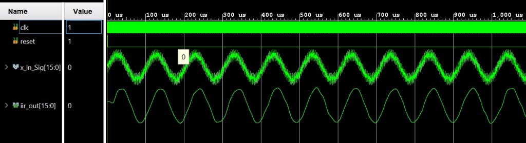
IIR Filter Simulation in Xilinx Vivado
The screen shot below shows the simulation of results of the this IIR filter. The input signal is a noisy 10 KHz sine wave. You notice there are some artifacts in the filtered output signal and this is due to the truncation and round off errors. The accuracy could have been improved by using a higher scale: we could have scaled the coefficients by 2^32, but the cost here is more memory, and possibly more other resources.
IIR Filter Improvement
Since it may not be desirable to increase the scaling value of the coefficients as it leads to usage of more memory and more FPGA resource. We need to break our IIR filter into cascaded Biquads. Our IIR filter is a 6th order filter, thus we will need to have three Biquads.
Stay turned, in the next posting I will demonstrate how to modify this code into a three Biquads filter for better frequency response accuracy. Below is a link to the complete code in My Github repo.
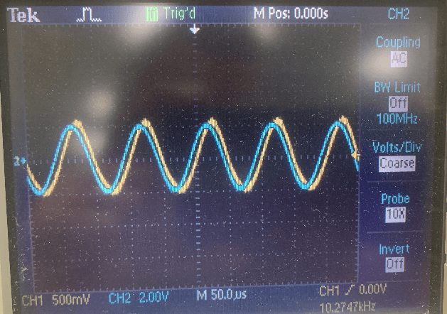
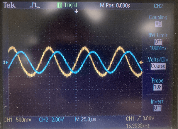
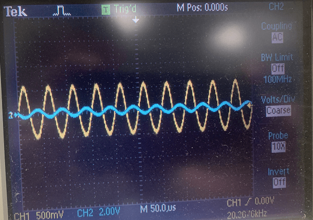
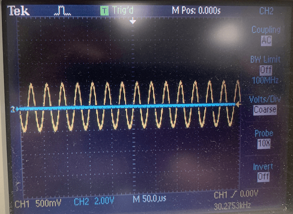
Real Time Data Measurements
The screen shots below are real time data captured on the oscilloscope. The yellow probe is the input while the blue probe is the output of the IIR filter taken at the output of a DAC.
First Image as an input frequency of 10KHz. Second image has an input of 15KHz, and third image has an input frequency of 20KHz. The last image has an input frequency of 30KHz.
You can see as the input frequency increases, the amplitude of the filtered signals gets attenuated more and more.
Source Code
A copy of the source code can be accessed from the link below:
👉 View VHDL IIR Filter Source Code in my GitHub Repository
Author: Farid M
