
In his post, I will talk about how to optimize the speed of the IIR filter designed in the previous posting. This new 6th order IIR can run at a clock speed of 400 MHz by using DSP slices.
The filter is structured as three cascaded biquad sections, optimized for low latency and high throughput. By leveraging the FPGA’s built-in DSP blocks for multiply-accumulate operations and applying deep pipelining techniques.
IIR difference equation
1. Direct‑form difference equation (6th order)
2. Transfer function
3. Cascade of three biquads
4. Per‑biquad difference equation
Implementation
As per the above Biquad difference equation, we need 5 multiplication-Addition operations plus another subtraction. To perform these math operations efficiently, I used Xilinix IpCore MultAdd and Adder IpCore. I will explain later how these IPCores are configured so that Vivado tool would use DSP48 slices are used. The VHDL code below shows the implementation of a single IIR Biquad. Each Biquad implementation needs 5 DSP slices to be used for multiplication-addition operations and another DSP slices to be used for subtraction. For a sixth order IIR, we need a total of 18 DSP slices (6 DSP slices per Biquad).
It should be noted here that each multiplication addition operation took THREE clock cycles, and an addition/subtraction takes Two clock cycles. In total it takes 21 clock cycles for complete a single Biquad computation, which include clocks needed for capturing the input data and shifting the incoming samples. With a system clock of 400 MHz, it took 52.5ns: as seem in the image below, and that is a total of 21 clock cycles per Biquad. For three biquads, it takes 63 clock cycles.

-- Process for updating the filter with pipelined calculations
     BiQAUD_PROCESS:process(clk, resetn)

     variable BiQuad_WaitClkCounter1 : integer range 0 to 4 := 0;  -- 3-clock cycle counter
     variable BiQuad_WaitClkCounter2 : integer range 0 to 4 := 0;  -- 3-clock cycle counter
     variable BiQuad_WaitClkCounter3 : integer range 0 to 4 := 0;  -- 3-clock cycle counter
     variable BiQuad_WaitClkCounter4 : integer range 0 to 3 := 0;  -- 3-clock cycle counter
     begin
         if resetn = '0' then

         -- Reset input and output registers to 0
         BiQuad_x_reg  (others => '0'));
         BiQuad_y_reg  (others => '0'));

         BiQuad_mul_x  (others => '0'));
         BiQuad_mul_y  (others => '0'));

         BiQuad_Sum_x  (others => '0'));
         BiQuad_Sum_y  (others => '0'));
         BiQuad_sample_valid_out <= '0';
         BiQuad_Output_NotShifted  '0');
         BiQuad_busy <= '0';

         MultAdd1_Subtract_sig <= '0';
         MultAdd2_Subtract_sig <= '0';
         MultAdd3_Subtract_sig <= '0';
         MultAdd4_Subtract_sig <= '0';
         MultAdd5_Subtract_sig <= '0';

         MultAdd1_sclr_sig <= '0';
         MultAdd2_sclr_sig <= '0';
         MultAdd3_sclr_sig <= '0';
         MultAdd4_sclr_sig <= '0';
         MultAdd5_sclr_sig <= '0';
         --BiQuad complete stages flags
         BiQuad_DoneStage1 <= '0';
         BiQuad_DoneStage2 <= '0';
         BiQuad_DoneStage3 <= '0';
         BiQuad_DoneStage4 <= '0';
         BiQuad_DoneStage5 <= '0';
         BiQuad_DoneStage6 <= '0';
         BiQuad_DoneStage7 <= '0';
         BiQuad_DoneStage8 <= '0';
         BiQuad_DoneStage9 <= '0';
         BiQuad_DoneStage10 <= '0';
         BiQuad_DoneStage11 <= '0';

         BiQuad_sample_valid_out <= '0';
         BiQuad_sample_valid_out <= '0';

         BiQuad_WaitClkCounter1 := 0;
         BiQuad_WaitClkCounter2 := 0;
         BiQuad_WaitClkCounter3 := 0;
         BiQuad_WaitClkCounter4 := 0;

         elsif rising_edge(clk) then

        ------------------BIQUAD LOGIC -------------------------

             ----BiQuad stage1 is started
             if sample_valid_in = '1' then
                 BiQuad_x_reg(0) <=  signed(x_in);
                 BiQuad_busy  <= '1';
                 BiQuad_DoneStage2 <= '1';
             end if;

             ----BiQuad stage2 is started
             if(BiQuad_DoneStage2 = '1') then
                 -- Implement the equations below:
                 -- BiQuad_mul_x(0)= BiQuad_x_reg(0) * BiQuad_B_Coef(0)
                 MultAdd1_ce_sig <='1';
                 MultAdd1_A_In <= std_logic_vector(BiQuad_x_reg(0));
                 MultAdd1_B_In <= std_logic_vector(BiQuad_B0_Coef);
                 MultAdd1_C_In  '0');
                 MultAdd1_Subtract_sig <= '0';
                 -- BiQuad_mul_y(1)= BiQuad_y_reg(1) * BiQuad_A_Coef(1)
                 MultAdd2_ce_sig <='1';
                 MultAdd2_A_In <= std_logic_vector(BiQuad_y_reg(1));
                 MultAdd2_B_In <= std_logic_vector(BiQuad_A1_Coef);
                 MultAdd2_C_In  '0');
                 MultAdd2_Subtract_sig <= '0';
                 BiQuad_DoneStage2 <= '0';   --reset BiQuad stage2 flag
                 BiQuad_DoneStage3 <= '1';
              end if;

                 --BiQuad stage3 is started
                 if(BiQuad_DoneStage3 ='1') then
                     BiQuad_WaitClkCounter1 :=  BiQuad_WaitClkCounter1 +1;   --start counter
                     if(BiQuad_WaitClkCounter1 = 4) then
                         BiQuad_mul_x(0)  <= signed(MultAdd1_P_Out);
                         BiQuad_mul_y(1)  <= signed(MultAdd2_P_Out);

                         BiQuad_WaitClkCounter1 := 0;
                         BiQuad_DoneStage3 <='0';
                         BiQuad_DoneStage4 <='1';    --BiQuad stage3 is completed
                     end if;
				 end if;

                 --BiQuad stage4 is started
                 if(BiQuad_DoneStage4 ='1') then
                     -- BiQuad_mul_x(1)= BiQuad_x_reg(1) * BiQuad_B_Coef(1) + BiQuad_mul_x(0)
                     MultAdd3_ce_sig <='1';
                     MultAdd3_A_In <= std_logic_vector(BiQuad_x_reg(1));
                     MultAdd3_B_In <= std_logic_vector(BiQuad_B1_Coef);
                     MultAdd3_C_In <= std_logic_vector(BiQuad_mul_x(0));
                     MultAdd3_Subtract_sig <= '0';
                     -- BiQuad_mul_y(2)= BiQuad_y_reg(2) * BiQuad_A_Coef(2) + BiQuad_mul_y(1)
                     MultAdd4_ce_sig <='1';
                     MultAdd4_A_In <= std_logic_vector(BiQuad_y_reg(2));
                     MultAdd4_B_In <= std_logic_vector(BiQuad_A2_Coef);
                     MultAdd4_C_In <=std_logic_vector(BiQuad_mul_y(1));
                     MultAdd4_Subtract_sig <= '0';

                     BiQuad_DoneStage4 <='0';
                     BiQuad_DoneStage5 <='1';    --BiQuad stage4 is completed

                 end if;
                -- BiQuad stage5 is started
                 if(BiQuad_DoneStage5 ='1') then
                     BiQuad_WaitClkCounter2 :=  BiQuad_WaitClkCounter2 +1;   --start counter
                     if(BiQuad_WaitClkCounter2 = 4) then
                         BiQuad_mul_x(1)<= signed(MultAdd3_P_Out);
                         BiQuad_mul_y(2) <= signed(MultAdd4_P_Out);

                         BiQuad_WaitClkCounter2 := 0;
                         BiQuad_DoneStage5 <='0';
                         BiQuad_DoneStage6 <='1';    --BiQuad stage5 is completed
                     end if;
                 end if;

                 --BiQuad stage6 is started
                 if(BiQuad_DoneStage6 ='1') then

                     -- BiQuad_mul_x(2)= BiQuad_x_reg(2) * BiQuad_B_Coef(2) + BiQuad_mul_x(1)
                     MultAdd5_ce_sig <='1';
                     MultAdd5_A_In <= std_logic_vector(BiQuad_x_reg(2));
                     MultAdd5_B_In <= std_logic_vector(BiQuad_B2_Coef);
                     MultAdd5_C_In <= std_logic_vector(BiQuad_mul_x(1));
                     MultAdd5_Subtract_sig <= '0';

                     BiQuad_DoneStage6 <='0';
                     BiQuad_DoneStage7 <='1';
				 end if;

                 ---BiQuad stage7 is started
                 if(BiQuad_DoneStage7 ='1') then
                     BiQuad_WaitClkCounter3 :=  BiQuad_WaitClkCounter3 +1;   --start counter
                     if(BiQuad_WaitClkCounter3 = 4) then
                         BiQuad_mul_x(2)<= signed(MultAdd5_P_Out);
                         MultAdd5_ce_sig <='0';

                         BiQuad_WaitClkCounter3 :=0;
                         BiQuad_DoneStage7 <='0';
                         BiQuad_DoneStage8 <='1';   --BiQuad stage7 is completed
                     end if;
                 end if;

                 ---BiQuad stage8 is started
                 if(BiQuad_DoneStage8 ='1') then
                     Adder1_A_In <= std_logic_vector(BiQuad_mul_x(2));
                     Adder1_B_In<=std_logic_vector(BiQuad_mul_y(2));
                     BiQuad_DoneStage8 <='0';
                     BiQuad_DoneStage9 <='1';
			     end if;

                 ---BiQuad stage9 is started
                 if(BiQuad_DoneStage9 ='1') then
                     BiQuad_WaitClkCounter4 :=  BiQuad_WaitClkCounter4 +1;
                     if(BiQuad_WaitClkCounter4 = 3) then
                         BiQuad_Output_NotShifted <=  signed(Adder1_S_out);

                         BiQuad_WaitClkCounter4 :=0;
                         BiQuad_DoneStage9 <='0';
                         BiQuad_DoneStage10 <='1';
                     end if;
                 end if;
                 --BiQuad stage10 is started
                 if(BiQuad_DoneStage10 ='1') then
                     BiQuad_y_reg(1) <= resize(shift_right(BiQuad_Output_NotShifted,SCALE),X_WIDTH);   --scale down by 2^24
                     BiQuad_Output_Shifted <= resize(shift_right(BiQuad_Output_NotShifted,SCALE),X_WIDTH);   --BiQuad_Output_Shifted;
                     BiQuad_y_reg(2) <= BiQuad_y_reg(1);

                 for i in 1 to 2 loop
                     BiQuad_x_reg(i) <= BiQuad_x_reg(i-1);
                 end loop;

                 BiQuad_sample_valid_out <= '1';

                 BiQuad_busy  <= '0';

                 BiQuad_DoneStage10 <='0';
                 BiQuad_DoneStage11 <='1';

                 end if;

                 ---BiQuad stage11 is started
                 if(BiQuad_DoneStage11 ='1') then
                     BiQuad_sample_valid_out <= '0';
                     BiQuad_busy  <= '0';
                     BiQuad_DoneStage11 <='0';
                 end if;
         end if;

end process;
BiQuad_out  <= BiQuad_Output_Shifted(15 downto 0) when (BiQuad_Output_Shifted  < -32768)
                                             AND (BiQuad_Output_Shifted<= 32767) else
                                             to_signed(-32768,16) when (BiQuad_Output_Shifted < -32768) else
                                             to_signed(32767,16) when (BiQuad_Output_Shifted< 32767);
sample_valid_out <=BiQuad_sample_valid_out;
end Behavioral;
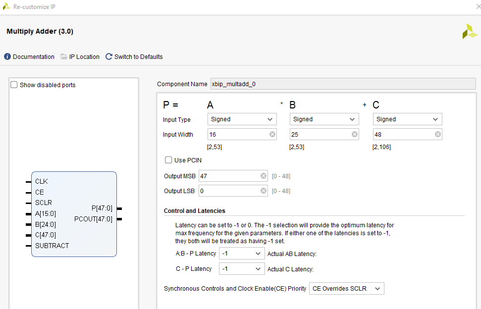
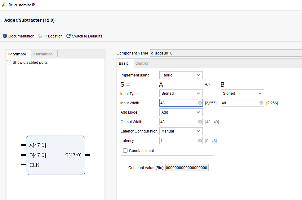
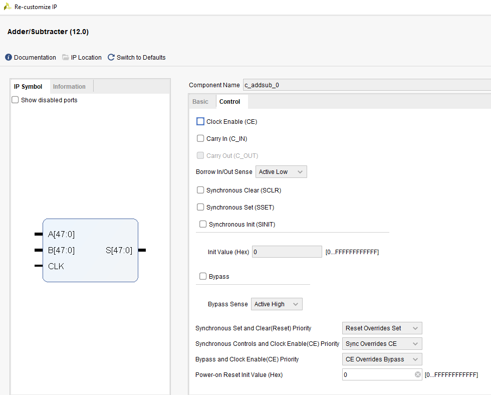
MultAdd and Adder IP Cores Configurations
Below are screen shots showing how we can configure the MultAdd and Adder IpCores.
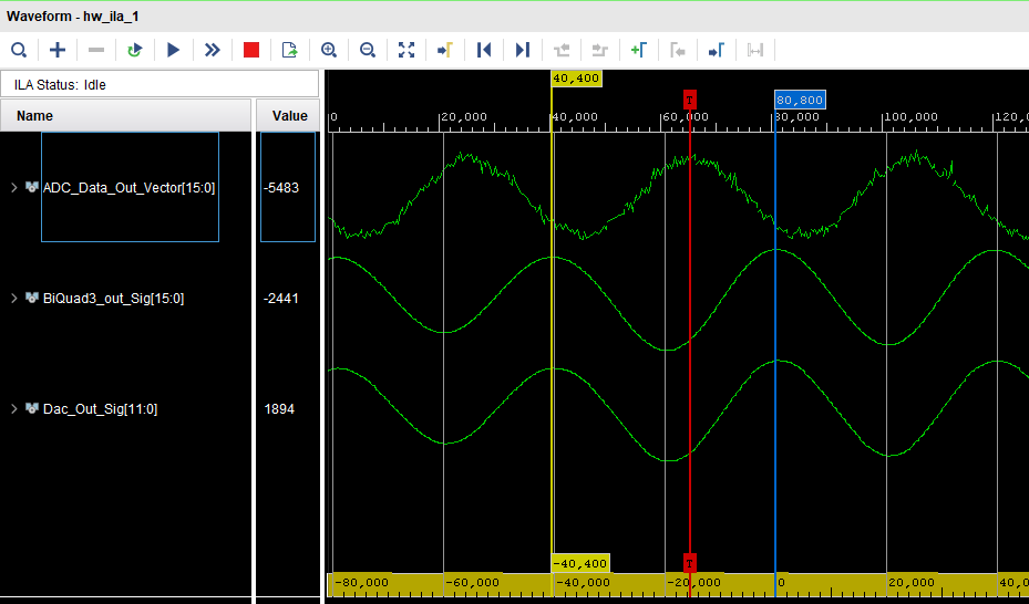
The image below shows the output of the filter: signal Dac_Out_Sig is the data for a filtered 10KHz signal sent to a DAC. You can notice that the input signal is captured with some noise, but after the filter, all the high frequency noise is removed..
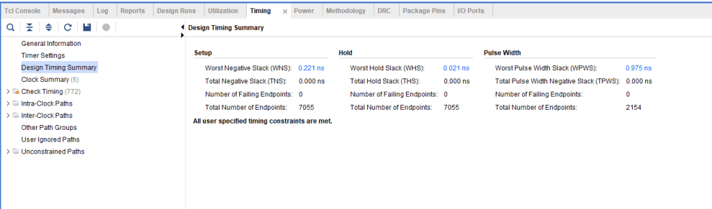
Timing Summary Report
Screen shot below shows the timing reports generated by Vivado for this IIR design. The design was implemented on Zync UntraScale development board ZCU102 which has this FPGA part number: xczu9eg-ffvb1156-1-e.
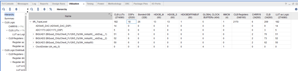
The image below shows the utilization report of this IIR filter implementation. In terms of DSP slices: it used 18 DSB slices, 6 DSP slices per Biquad filter: 5 DSP slices were used for multiplication addition operations and one DSP used for the subtraction operation as per the form I equation for an IIR filter.
Source Code
If anyone is interested in the source code, feel free to message me in the comments.
