
Author: Farid M, https://embeddeddesign.org/
Introduction
In modern signal processing and communication systems, generating precise frequency sweeps is a common requirement. One effective method for achieving this is through Direct Digital Synthesis (DDS), a technique that allows for the generation of high-quality, tunable waveforms across a wide range of frequencies. DDS offers exceptional accuracy and flexibility, making it ideal for applications such as testing, signal generation, and frequency modulation.
In this blog, we will explore how to implement a frequency sweep using DDS in VHDL, leveraging the powerful capabilities of Xilinx’s IP core. By the end of this guide, you will have a clear understanding of how to configure and use Xilinx’s DDS compiler to generate frequency sweeps, how to modify the generated VHDL code to fit your project requirements, and how to integrate it into an FPGA-based system for real-world applications.
Whether you are new to DDS or looking to implement advanced frequency control in your designs, this tutorial will provide step-by-step guidance on how to harness the full potential of DDS within the Xilinx ecosystem.
Tools Used
For this project, the following tools were used:
- Xilinx Vivado: Vivado is an integrated development environment (IDE) from Xilinx that provides the necessary tools for FPGA design, including synthesis, simulation, and debugging. It is the core platform used for creating and implementing FPGA designs.
- Xilinx DDS IP Core: The Xilinx DDS (Direct Digital Synthesis) IP core is a powerful, flexible block that allows for efficient waveform generation. It is used here to generate the frequency sweep for signal processing applications.
Theory Behind DDS Frequency Calculation
- At the heart of Direct Digital Synthesis (DDS) is a mathematical relationship that determines the output frequency of the generated waveform. This relationship is governed by the formula:
fout = (Phase Increment / 2N) × fclkWhere:
- fout is the output frequency of the waveform (in Hz).
- Phase Increment is the numeric step added to the phase accumulator each clock cycle.
- N is the number of bits in the phase accumulator (commonly 32 bits).
- Fclk is the clock frequency driving the DDS (in Hz).
The DDS works by using a phase accumulator that is incremented by a fixed value (Phase_Increment) every clock cycle. This accumulated phase is then mapped to a sine wave using a lookup table. The faster the phase accumulates, the higher the output frequency. Because the phase accumulator wraps around (modulo 2N), the frequency is linearly related to the increment value.
In our implementation, we configured the DDS to generate a frequency sweep starting from 5 kHz and reaching up to 500 kHz. This was achieved by varying the Phase_Increment value. For instance, selecting an increment of 13,450 resulted in a specific frequency within this range, based on the clock frequency and accumulator width.
This method provides extremely fine resolution, enabling precise control over output frequency — a key requirement in signal generation, modulation, and testing applications.
Figure 1: Digital Phase Wheel
Phase Increment vs. Output Frequency Table
The table below illustrates the calculation of 10 steps for a sweep from around 1KHz to 10 KHz. Each step increases the frequency by 5KHz. In our case we have 10 Step. In the VHDL code below, the implementation is done for 500 steps which corresponds to max frequency of 500KHz.
- fout is the output frequency of the waveform (in Hz).
- Ph Inc is the phase increment which is the numeric step added to the phase accumulator each clock cycle.
- N is the number of bits in the phase accumulator (commonly 32 bits).
- fclk is the clock frequency driving the DDS (in Hz).
| fout (KHz) | Clk | N | Ph Incr | Step |
|---|---|---|---|---|
| 1.00210309 | 100000000 | 28 | 2690 | 1 |
| 2.00420618 | 100000000 | 28 | 5380 | 2 |
| 3.00630927 | 100000000 | 28 | 8070 | 3 |
| 4.00841236 | 100000000 | 28 | 10760 | 4 |
| 5.01051545 | 100000000 | 28 | 13450 | 5 |
| 6.01261854 | 100000000 | 28 | 16140 | 6 |
| 7.01472163 | 100000000 | 28 | 18830 | 7 |
| 8.01682472 | 100000000 | 28 | 21520 | 8 |
| 9.01892781 | 100000000 | 28 | 24210 | 9 |
| 10.02103090 | 100000000 | 28 | 26900 | 10 |
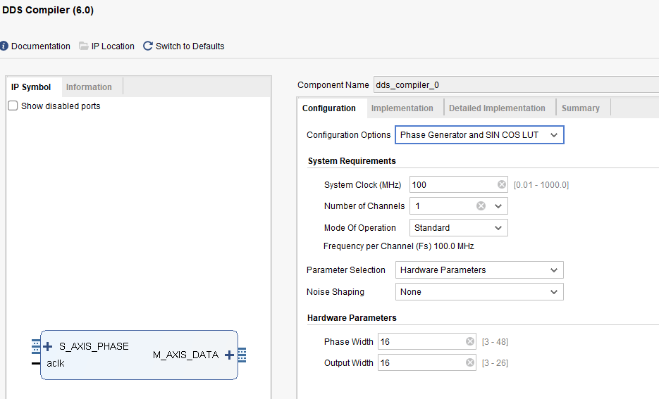
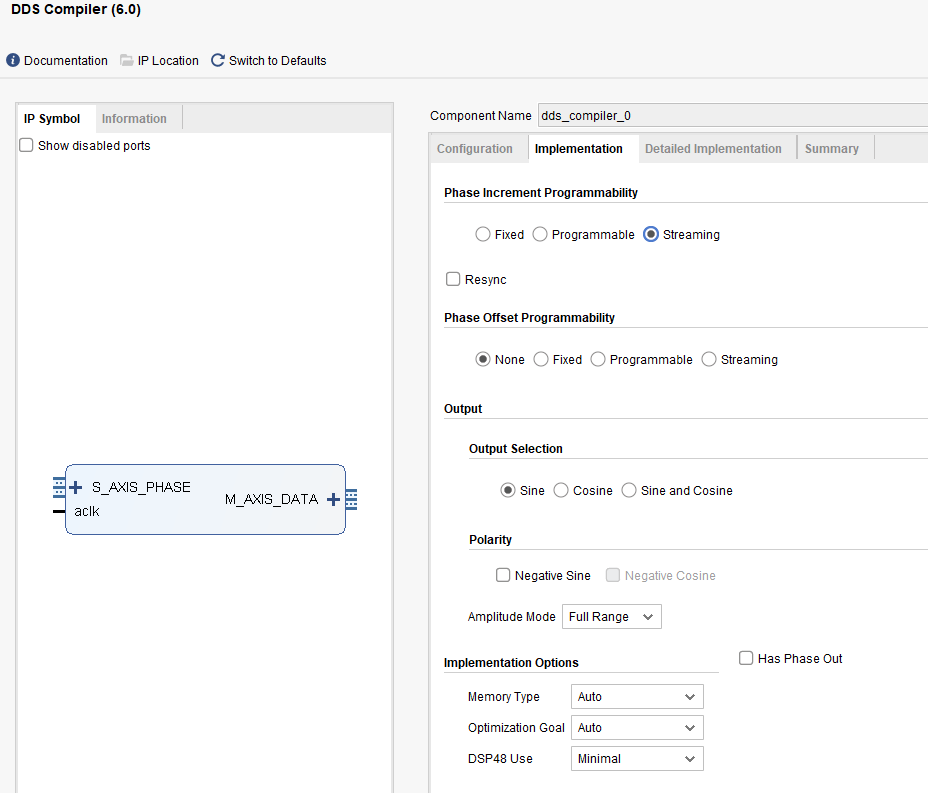
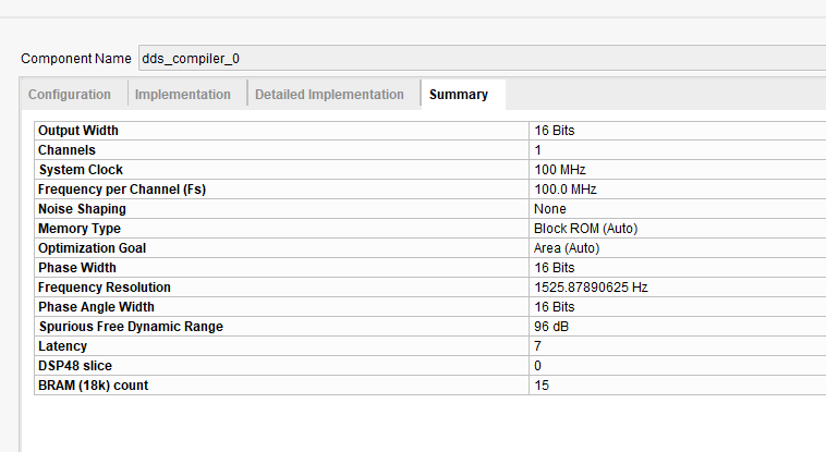
Configuring the DDS IP Core for a 100 MHz System Clock
Please see the images below to understand how we configured the Xilinx DDS IP core to generate a sine‑wave sweep with a 100 MHz system clock; note that the IP core’s output interface is an AXI‑Stream, which allows seamless streaming of the generated waveform data into downstream processing blocks.

DDS State Machine Implementation in VHDL
Below is the top‑level VHDL source used to drive the Xilinx DDS Compiler IP core, perform the frequency sweep, and stream the output over AXI‑Stream:
----------------------------------------------------------------------------------
-- Company:
-- Engineer: Farid M
-- Design Name:
-- Module Name: TopLevel - Behavioral
-- Revision 0.01 - File Created
-- Additional Comments:
----------------------------------------------------------------------------------
library IEEE;
use IEEE.STD_LOGIC_1164.ALL;
use ieee.numeric_std.all;
use IEEE.STD_LOGIC_UNSIGNED.all;

entity DDS_Sweep_TopLevel is
port (
   clk                 : in std_logic := '0';  --system cock running at 399.68MHz
   ce                  : in std_logic;
   reset               : in std_logic;
   s_axis_phase_tready : OUT STD_LOGIC;
   m_axis_phase_tdata  : OUT STD_LOGIC_VECTOR(31 DOWNTO 0);
   m_axis_data_tdata   : OUT STD_LOGIC_VECTOR(15 DOWNTO 0)
);
end DDS_Sweep_TopLevel;

architecture Behavioral of DDS_Sweep_TopLevel is

-- Define a 2-bit counter for dividing the clock by 4
signal clk_counter2 : STD_LOGIC_VECTOR(7 downto 0) := "00000000";  -- 2-bit counter (max value = 3)

signal Counter             : integer range 0 to 399840 := 0;   -- 19 bits for update counter used to change the frequency

--constant UpdateFreqCounter : integer := 99840;  --about one miliseconds with DDS_clk


signal s_axis_phase_tvalid_sig : std_logic :='0';
signal s_axis_phase_tdata_Sig  : STD_LOGIC_VECTOR(31 DOWNTO 0):="00000000000000000000000000000000";
signal m_axis_data_tready_Sig  : std_logic:='0';
signal m_axis_data_tvalid_Sig  : std_logic;


 -- State machine state
 signal state : integer := 0;

 -- Declare signals instead of variables
signal PhaseIncrConstant : integer := 13450;       -- Initialize PhaseIncrConstant
signal freq_phase_incr   : integer := 0;           -- Initialize freq_phase_incr
signal FreqSweepCnt      : integer := 1;           -- Initialize FreqSweepCnt
signal period_wait_cnt   : integer := 0;           -- Initialize period_wait_cnt
signal chirp_loop_cntr   : integer := 0;           -- Initialize chirp_loop_cntr
signal freq_period       : integer := 20000;       -- Initialize freq_period


------------- Begin Cut here for COMPONENT Declaration ------ COMP_TAG
COMPONENT dds_compiler_0
  PORT (
    aclk : IN STD_LOGIC;
    s_axis_phase_tvalid : IN STD_LOGIC;
    s_axis_phase_tdata : IN STD_LOGIC_VECTOR(31 DOWNTO 0);
    m_axis_data_tvalid : OUT STD_LOGIC;
    m_axis_data_tdata : OUT STD_LOGIC_VECTOR(15 DOWNTO 0)
  );
END COMPONENT;

begin

DDS_Sweep : dds_compiler_0
  PORT MAP (
    aclk => clk,
    s_axis_phase_tvalid => s_axis_phase_tvalid_Sig,
    s_axis_phase_tdata => s_axis_phase_tdata_Sig,
    m_axis_data_tvalid => m_axis_data_tvalid_Sig,
    m_axis_data_tdata => m_axis_data_tdata

  );


  -- Frequency Sweep Process (Update frequency based on counter)
  process(clk, reset)
  begin
    if reset = '1' then
        -- Reset the frequency sweep counter and output clock signal
        FreqSweepCnt <= 0; -- this keeps track of how may frequencies generated so far
        s_axis_phase_tvalid_sig <= '0';
        m_axis_data_tready_Sig  <= '0';

       s_axis_phase_tvalid_sig <='0';
       s_axis_phase_tdata_Sig  <="00000000000000000000000000000000";
       m_axis_data_tready_Sig <= '0';

       state <= 0;

    elsif rising_edge(clk) then

      case state is

      when 0 =>
            s_axis_phase_tvalid_sig <= '0';
            m_axis_data_tready_Sig  <= '0';
            period_wait_cnt   <= 0;
            chirp_loop_cntr   <= 0;
            state <= 1;

       when 1 =>
            Freq_phase_incr <= FreqSweepCnt * PhaseIncrConstant;  -- gives us the value to load to the DDS
            state <= 2;

       when 2 =>
             s_axis_phase_tvalid_sig <= '1';                  ---per PG141 - tvalid is set before tready goes high
             state <= 3;

        when 3 =>
             m_axis_data_tready_Sig  <= '1';
             s_axis_phase_tdata_Sig <= std_logic_vector(resize(to_unsigned(Freq_phase_incr, 32), 32));
             state <= 4;

       when 4 =>
            if (period_wait_cnt >= freq_period) then
                period_wait_cnt <= 0;
                chirp_loop_cntr <= chirp_loop_cntr + 1;
                state <= 5;   --keep track of loop counter
             else
                period_wait_cnt <= period_wait_cnt + 1;
                state <= 4;
             end if;

       when 5 =>

          if(FreqSweepCnt = 101) then --instead of 26
               chirp_loop_cntr <= 0;
               freq_phase_incr <= 0;
               PhaseIncrConstant <= 13450; --2684354; --   3361;
               FreqSweepCnt      <= 1;
               freq_phase_incr   <= 0;
               state <= 0;
           else
              chirp_loop_cntr <= chirp_loop_cntr + 1;
              FreqSweepCnt <= FreqSweepCnt + 1; --update for next cyc
              s_axis_phase_tvalid_sig <= '1';  -- Signal data not valid
              m_axis_data_tready_Sig  <= '1';

              state <= 0;

            end if;

        when others =>
             state <= 0;
    end case;
  end if;

  end process;

end Behavioral;
Simulation Results
To verify our DDS sweep, we ran a behavioral simulation in Vivado and captured the AXI‑Stream output. The waveform below shows the 5 kHz→500 kHz sweep over the configured time period.

Figure 7: DDS IP Core Simulation
💻 View the Source Code
The link below provides a complete VHDL DDS (Direct Digital Synthesis) sweep example designed to generate a frequency sweep from 5 kHz to 500 kHz, with each step increasing the frequency by 5 kHz.
Note the phase increment value of 13,450, which was calculated using the formula:fout = (Phase Increment / 2N) × fclk
Also, observe that the dwell time (the time spent at each frequency step) is set to 2000 × 10 ns, which corresponds to one full period of a 5 kHz signal.
Applications & Next Steps
Direct Digital Synthesis (DDS) is widely used in real‑world systems where precise, agile frequency control is required. Common applications include:
- Software‑Defined Radio (SDR): DDS provides tunable local oscillators for up/down conversion with very fine frequency resolution.
- Function & Signal Generators: Lab instruments use DDS to generate clean sine, square, and arbitrary waveforms across wide frequency ranges.
- Radar & Sonar: Frequency‑modulated continuous‑wave (FMCW) radars rely on DDS sweeps for accurate range and velocity measurements.
- Biomedical Imaging: Ultrasound systems employ DDS to create frequency‑swept pulses for high‑resolution tissue imaging.
- Spectrum Analyzers: DDS can act as a swept‑source for measuring frequency response in RF test equipment.
Stay tuned! In our next post, we’ll show how to integrate this DDS-based sweep into the validation of an IIR filter—complete with simulation results and performance analysis.
Should you have any comments or questions please email me, or leave them in the comments section.
