
Introduction
In this project, I demonstrate a complete FM demodulation system implemented on a Spartan-7 FPGA, where a 10.7 MHz FM-modulated RF signal is digitized and fully recovered in the digital domain.
The system uses an ADC1173 sampling at 10 MHz, intentionally operating in a bandpass undersampling concept to directly alias the RF input into an intermediate frequency (IF), eliminating the need for a traditional analog mixer stage.
After sampling, the aliased IF signal is digitally downconverted to baseband using quadrature mixing with a DDS-generated local oscillator. This process preserves both amplitude and phase information, which is essential for accurate FM demodulation.
The resulting complex baseband signal is processed through a multistage digital filtering and decimation chain using FIR filters, reducing the sampling rate while removing out-of-band spectral components and improving signal quality.
Finally, the system implements a discrete-time FM demodulator based on phase differentiation, enabling efficient recovery of the original modulating (audio) signal using FPGA-friendly arithmetic operations.
Overall, this project demonstrates how a complete RF receiver chain can be implemented entirely in the digital domain using undersampling theory, digital downconversion, multirate signal processing, and FPGA-based DSP techniques.
FM Demodulation System Block Diagram
The figure below illustrates the complete FM demodulation system implemented on the FPGA. All key design specifications and processing stages are included for clarity.
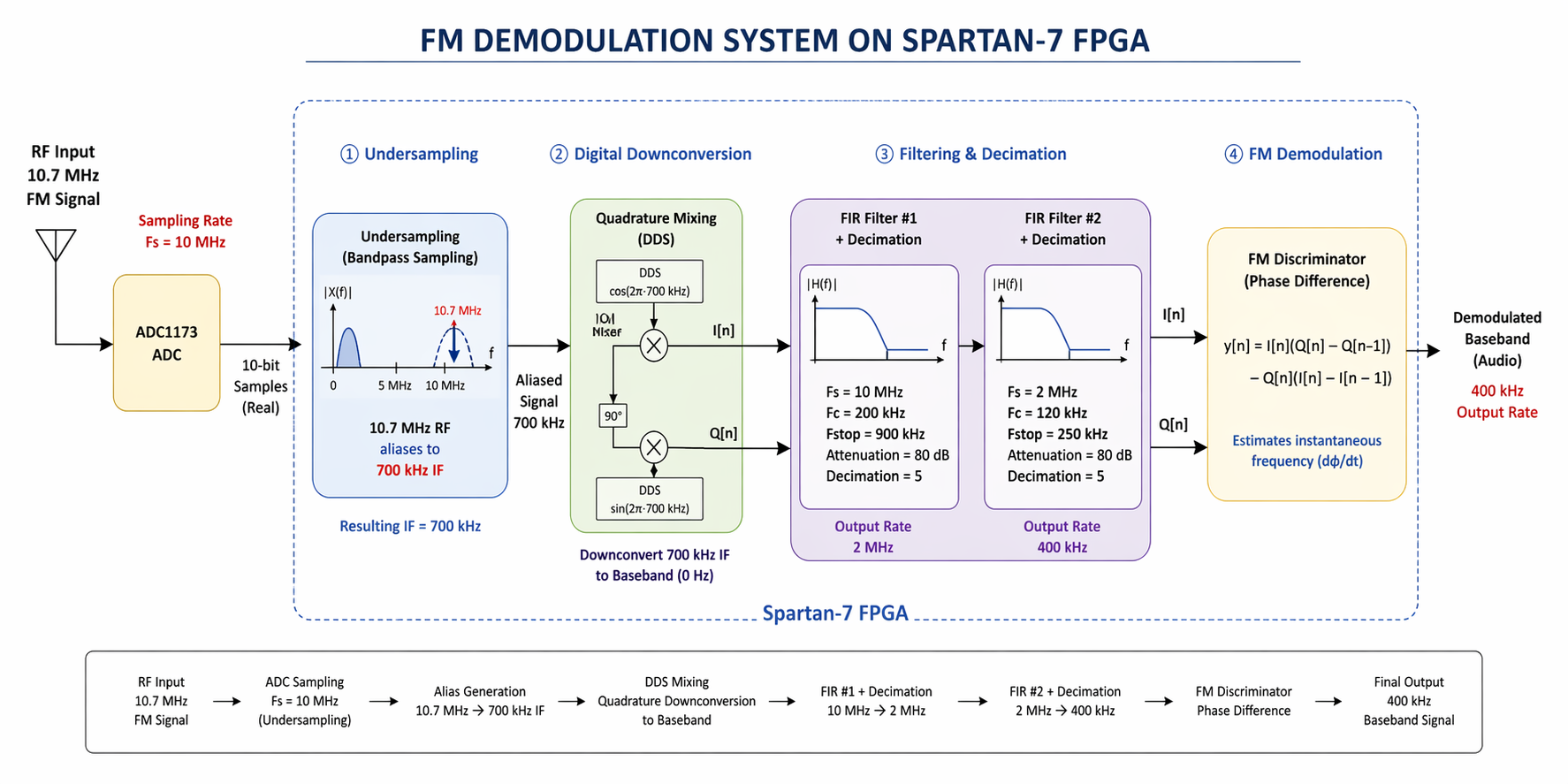
Figure 1: FM Demodulation System Block Diagram
Digital Implementation
1. Undersampling Principle (Bandpass Sampling)
Normally, a 10.7 MHz signal would require a sampling rate above 21.4 MHz. However, in bandpass sampling (undersampling), a band-limited RF signal can be sampled below the Nyquist rate as long as:
- The signal bandwidth is narrow enough
- Aliased spectral images do not overlap
Instead of preserving absolute frequency, undersampling preserves the information content of the signal. After sampling, the signal folds into the first Nyquist zone, producing an aliased intermediate frequency (IF).
Given:
Fs = 10 MHz
FRF = 10.7 MHz
Resulting IF ≈ 700 kHz
This occurs because the spectrum is mirrored around multiples of the sampling frequency. The alias frequency is given by:
fIF = | fRF − N · Fs |
For N = 1:
fIF = |10.7 MHz − 10 MHz| = 0.7 MHz
2. Digital Downconversion (DDC)
After sampling, the signal is centered at 700 kHz IF instead of baseband. To recover the original modulation, the FPGA performs digital mixing.
2.1 Quadrature Mixing Using DDS
The 700 kHz aliased signal is multiplied with a quadrature local oscillator (LO) generated by a DDS:
- cos(2π · 700 kHz)
- sin(2π · 700 kHz)
This produces:
- In-phase component I[n]
- Quadrature component Q[n]
This step shifts the signal from IF (700 kHz) down to baseband (0 Hz) while preserving phase information required for FM demodulation.
3. Digital Filtering and Decimation Chain
After downconversion, the signal is still sampled at 10 MHz. FIR filtering and decimation are used to reduce data rate and remove unwanted spectral components.
3.1 First FIR Filter + Decimation
- Sampling rate: 10 MHz
- Cutoff frequency: 200 kHz
- Stopband frequency: 900 kHz
- Attenuation: 80 dB
- Decimation factor: 5
Purpose:
- Remove high-frequency mixing products
- Keep only near-baseband FM information
- Reduce sampling rate
Output rate: 2 MHz
3.2 Second FIR Filter + Decimation
- Sampling rate: 2 MHz
- Cutoff frequency: 120 kHz
- Stopband frequency: 250 kHz
- Attenuation: 80 dB
Purpose:
- Further clean the baseband FM signal
- Remove residual high-frequency noise
- Prepare signal for FM demodulation stage
4. FM Demodulation in FPGA
After filtering, the signal exists in complex form:
- I[n] (in-phase)
- Q[n] (quadrature)
4.1 Discrete FM Discriminator
y[n] = I[n](Q[n] − Q[n−1]) − Q[n](I[n] − I[n−1])
4.2 Function
This computes phase change over time without using arctangent operations. It approximates:
d/dt (tan⁻¹(Q/I))
4.3 Advantages
- No CORDIC required
- Efficient FPGA implementation
- High-speed operation
- Robust to amplitude variations
5. Final Output
After the second decimation stage, the final output rate is: 400 kHz
This signal represents the recovered baseband audio/modulating signal using:
- Undersampling
- Digital downconversion
- FIR filtering
- Phase-based FM demodulation
Top-Level VHDL: FM Radio Demodulation System (Spartan-7)
library ieee;
use ieee.std_logic_1164.all;
use ieee.numeric_std.all;

entity FM_Radio_S7_TL is
  port (
    CLK100MHZ     : in  STD_LOGIC;
    ADC_Clk_10MHz : out std_logic;
    reset         : in  STD_LOGIC;

    ADC_Data_In   : in std_logic_vector(7 downto 0);

    Dac_Out       : out std_logic_vector(11 downto 0);
    ChipSeclect_n : out STD_LOGIC;
    WriteEnable   : out STD_LOGIC
  );
end FM_Radio_S7_TL;

architecture behavioral of FM_Radio_S7_TL is

signal clk200MHz                : std_logic;
signal clk400MHz                : std_logic;
signal clk10MHz                 : std_logic;
signal clk                      : std_logic := '0';
signal clk_aux                  : std_logic := '0';
signal clk20MHz                 : std_logic := '0';

signal ADC_Data_Out_IntSig      : std_logic_vector(7 downto 0) := (others => '0');
signal ADC_Data_Out_Vector      : std_logic_vector(7 downto 0);

signal locked_Sig               : std_logic;
signal DDS0_tvalid_out          : std_logic;
signal QuadratureSignal         : std_logic_vector(15 downto 0);
signal QuadratureSignal_dly     : std_logic_vector(15 downto 0);
signal IMixerWaveform           : std_logic_vector(7 downto 0);
signal QMixerWaveform           : std_logic_vector(7 downto 0);
signal IMixedFMSignal           : std_logic_vector(15 downto 0);
signal QMixedFMSignal           : std_logic_vector(15 downto 0);
signal FMsignal                 : std_logic_vector(31 downto 0);
signal FMsignal_sys             : std_logic_vector(67 downto 0);
signal FMsignal_sys_scaled      : std_logic_vector(31 downto 0);

signal FMsignal_16Bits_Signed   : std_logic_vector(15 downto 0);
signal FM_TestSignal            : std_logic_vector(15 downto 0);


signal ADC_Data_Valid_Out       : std_logic;
signal ADC_Data_Valid_Out_dly1  : std_logic;
signal ADC_Data_Valid_Out_dly2  : std_logic;

signal DDS1_tvalid_out          : std_logic;
signal MultAdd_In_valid         : std_logic;
signal MessageTone_Signal       : std_logic_vector(15 downto 0);
signal MessageCarrierMultiplied : std_logic_vector(31 downto 0);

signal MessageCarrierMultipliedScaled  : std_logic_vector(15 downto 0);
signal AM_ModulatedSignal              : std_logic_vector(15 downto 0);
signal QuadratureSignalWithOffset      : std_logic_vector(15 downto 0);
signal DDSsim_data_tvalid              : std_logic;

signal MixerSineSignal                 : std_logic_vector(7 downto 0);
signal MixerCosineSignal               : std_logic_vector(7 downto 0);
signal MixerSine_tvalid                : std_logic;
signal MixerCosine_tvalid              : std_logic;

signal Tvalidfortest                   : std_logic;

signal counter1                        : integer range 0 to 1 := 0;     -- counter for decimation

signal AM_ModulatedSignal_Decimated    : std_logic_vector(11 downto 0); -- decimated output
signal sample_valid                    : std_logic := '0';              -- output valid signal

signal AM_ModulatedSignalScaled        : std_logic_vector(11 downto 0);
signal AM_ModulatedSig_WithOffset      : std_logic_vector(15 downto 0);

signal Dac_Out_Sig         : std_logic_vector(11 downto 0);
signal ChipSeclect_n_sig   : std_logic := '0';
signal DACSample_Sig       : std_logic := '0';
signal WriteEnable_IntSig  : std_logic:= '0';

-- State machine state
signal state : integer := 0;


signal adc_sync1    :std_logic_vector( 7 downto 0):="00000000";
signal adc_sync_Sig :std_logic_vector( 7 downto 0):="00000000";

signal adc_sync2 :std_logic_vector( 7 downto 0);
signal adc_sync3 :std_logic_vector( 7 downto 0);

signal clk_and_CE :std_logic_vector(1 downto 0):="00";
signal MixerClkEnable_ILA :std_logic_vector(0 downto 0):= "0";

--DEMODULATION
signal DDS2_data_tvalid           : std_logic:= '0';
signal DD2_QuadratureSignal       : std_logic_vector( 15 downto 0);
signal AM_Sig_Carrier_Multiplied  : std_logic_vector( 23 downto 0);
signal FIR_Valid_in               : std_logic:= '0';
signal FIR_Valid_in_Sig           : std_logic:= '0';

signal I_FIR_data_tready          : std_logic:= '0';
signal I_FIR_data_tvalid          : std_logic:= '0';
signal Q_FIR_data_tready          : std_logic:= '0';
signal Q_FIR_data_tvalid          : std_logic:= '0';

signal FIR_Data_in                : STD_LOGIC_VECTOR(15 DOWNTO 0);
signal FIR_Data_in_Sig            : STD_LOGIC_VECTOR(15 DOWNTO 0);
signal IMixed_After_FIR           : STD_LOGIC_VECTOR(39 DOWNTO 0);
signal QMixed_After_FIR           : STD_LOGIC_VECTOR(39 DOWNTO 0);

signal I_FIRSig_ScaledDwn         : STD_LOGIC_VECTOR(33 DOWNTO 0);
signal Q_FIRSig_ScaledDwn         : STD_LOGIC_VECTOR(33 DOWNTO 0);
signal IQ_Signal_ScaledDwn        : STD_LOGIC_VECTOR(31 DOWNTO 0);

signal IQ_Signal                  : STD_LOGIC_VECTOR(31 DOWNTO 0);

signal ADC_Data_tvalid            : std_logic:= '0';
signal DDS_Data_tvalid            : std_logic:= '0';
signal Multiplier_Data_Out_Valid  : std_logic;

signal ADC_Data_Out_IntSig_16Bits       : STD_LOGIC_VECTOR(15 DOWNTO 0);
signal CarrierFrequency_32Bits          : STD_LOGIC_VECTOR(31 DOWNTO 0);
signal AM_Sig_Carrier_Multiplied_48Bits : STD_LOGIC_VECTOR(47 DOWNTO 0);

signal MixerClk       : std_logic:= '0';
signal MixerState     : integer := 0;

signal MixerClkEnable  : std_logic:= '0';

signal clk10MHz_Dly   : std_logic:= '0';
signal clk10MHzz      : std_logic:= '0';

signal CarrierFrequency_sync1  :std_logic_vector(15 downto 0);
signal CarrierFrequency_sync2  :std_logic_vector(15 downto 0);

signal slow_d1, slow_d2,slow_d3, slow_mid : std_logic := '0';
signal pulse_4clk                         : std_logic := '0';
signal fir_valid_sync1, fir_valid_sync2   : std_logic;

signal fir_valid_d     : std_logic;
signal fir_valid_200   : std_logic;
signal stretch_cnt     : integer range 0 to 1 := 0;
signal BitVal          : unsigned(0 downto 0):= (others => '0');
signal slow_pulse      : std_logic;

signal In_data         :std_logic_vector(15 downto 0);
signal Qn_data         :std_logic_vector(15 downto 0);
signal In_16bits       :std_logic_vector(15 downto 0);
signal Qn_16bits       :std_logic_vector(15 downto 0);

signal ADC_data_input        :std_logic_vector(7 downto 0);
signal FM_out_scaled         : std_logic_vector(11 downto 0):= (others => '0');
signal counter               : integer range 0 to 499 := 0;
signal DAC_in_pulse          : std_logic:= '0';

signal counter2 : unsigned(8 downto 0) := (others => '0'); -- enough for 0-249
signal clk400KHz : std_logic := '0';

signal Q_FIR2_data_tready : std_logic := '0';
signal Q_FIR2_data_tvalid : std_logic := '0';
signal QMixed_After_FIR2  : STD_LOGIC_VECTOR(55 DOWNTO 0);
signal I_FIR2_data_tready : std_logic := '0';
signal I_FIR2_data_tvalid : std_logic := '0';
signal IMixed_After_FIR2  : STD_LOGIC_VECTOR(55 DOWNTO 0);

signal FMsignal_12Bits : STD_LOGIC_VECTOR(11 DOWNTO 0);


COMPONENT fm_demod_0
  PORT (
    q_in : IN STD_LOGIC_VECTOR(32 DOWNTO 0);
    i_in : IN STD_LOGIC_VECTOR(32 DOWNTO 0);
    reg_en : IN STD_LOGIC;
    clk : IN STD_LOGIC;
    fm_demodulated : OUT STD_LOGIC_VECTOR(67 DOWNTO 0)
  );
END COMPONENT;

COMPONENT iq_fir_0
  PORT (
    in1 : IN STD_LOGIC_VECTOR(15 DOWNTO 0);
    in2 : IN STD_LOGIC_VECTOR(15 DOWNTO 0);
    clk : IN STD_LOGIC;
    fir_out_q : OUT STD_LOGIC_VECTOR(32 DOWNTO 0);
    fir_out_i : OUT STD_LOGIC_VECTOR(32 DOWNTO 0);
    i_tvalid : OUT STD_LOGIC;
    q_data_tready : OUT STD_LOGIC;
    q_data_tvalid : OUT STD_LOGIC;
    i_data_tready : OUT STD_LOGIC
  );
END COMPONENT;

--COMPONENT fm_demod_0
--  PORT (
--    q_in : IN STD_LOGIC_VECTOR(32 DOWNTO 0);
--    i_in : IN STD_LOGIC_VECTOR(32 DOWNTO 0);
--    reg_en : IN STD_LOGIC;
--    clk : IN STD_LOGIC;
--    fm_demodulated : OUT STD_LOGIC_VECTOR(67 DOWNTO 0)
--  );
--END COMPONENT;

component clk_wiz_0
port
 (
  clk_out1          : out    std_logic;
  clk_out2          : out    std_logic;
  locked            : out    std_logic;
  clk_in1           : in     std_logic
 );
end component;


--this DDS generates the Cosine signal of 700KHz
COMPONENT dds_compiler_0
  PORT (
    aclk : IN STD_LOGIC;
    m_axis_data_tvalid : OUT STD_LOGIC;
    m_axis_data_tdata  : OUT STD_LOGIC_VECTOR(7 DOWNTO 0)
  );
END COMPONENT;

--this DDS generates negative sine signal of 700KHz
COMPONENT dds_compiler_1
  PORT (
    aclk : IN STD_LOGIC;
    m_axis_data_tvalid : OUT STD_LOGIC;
    m_axis_data_tdata : OUT STD_LOGIC_VECTOR(7 DOWNTO 0)
  );
END COMPONENT;

--This is the mixer: mixes FM signal with +cosine and -sine
COMPONENT mult_gen_0
  PORT (
    CLK : IN STD_LOGIC;
    A   : IN STD_LOGIC_VECTOR(7 DOWNTO 0);
    B   : IN STD_LOGIC_VECTOR(7 DOWNTO 0);
    CE  : IN STD_LOGIC;
    P   : OUT STD_LOGIC_VECTOR(15 DOWNTO 0)
  );
END COMPONENT;

--FIR with Deccimation:
--Fs= 10MHz; Fc= 200KHz, Fstop=900KHz; Attenuation= 80dB
--Decimation: 5; output rate is: 2MHz
COMPONENT fir_compiler_0
  PORT (
    aclk               : IN STD_LOGIC;
    s_axis_data_tvalid : IN STD_LOGIC;
    s_axis_data_tready : OUT STD_LOGIC;
    s_axis_data_tdata  : IN STD_LOGIC_VECTOR(15 DOWNTO 0);
    m_axis_data_tvalid : OUT STD_LOGIC;
    m_axis_data_tdata  : OUT STD_LOGIC_VECTOR(39 DOWNTO 0)
  );
END COMPONENT;

--FIR with Deccimation:
--Fs= 2MHz; Fc= 120KHz, Fstop=250KHz; Attenuation= 80dB
--Decimation: 5; output rate is: 400 KHz
COMPONENT fir_compiler_1
  PORT (
    aclk : IN STD_LOGIC;
    s_axis_data_tvalid : IN STD_LOGIC;
    s_axis_data_tready : OUT STD_LOGIC;
    s_axis_data_tdata : IN STD_LOGIC_VECTOR(39 DOWNTO 0);
    m_axis_data_tvalid : OUT STD_LOGIC;
    m_axis_data_tdata : OUT STD_LOGIC_VECTOR(55 DOWNTO 0)
  );
END COMPONENT;

--This is the FM demodulator
COMPONENT FM_Demodulation
PORT (
    clock         : in STD_LOGIC;
    reset         : in STD_LOGIC;
    data_tvalid   : in STD_LOGIC;

    In_data        : in std_logic_vector(39 downto 0);
    Qn_data        : in std_logic_vector(39 downto 0);

    DemodSignal   : out std_logic_vector(31 downto 0)
  );
END COMPONENT;

--ADC for sampling the FM signal at 10MHz
COMPONENT ADC1173_DSP
port(
    ADC_Clk                 : in std_logic;
    Clk_fast                : in std_logic; --200MHz
    reset                   : in std_logic;
    ADC_Data_In             : in std_logic_vector(7 downto 0);
    ADC_Data_Valid          : out std_logic;
    ADC_Data_In_out         : out std_logic_vector(7 downto 0)
);
end component;

--ILA for hardware validation
COMPONENT ila_0
PORT (
    clk    : IN STD_LOGIC;
    probe0 : IN STD_LOGIC_VECTOR(15 DOWNTO 0)
);
END COMPONENT;


begin


Clk_Wizard: clk_wiz_0
   port map (
   clk_out1 => clk200MHz,
   clk_out2 => clk10MHz,

   locked   => locked_Sig,
   clk_in1  => CLK100MHZ
 );

 ADC_Clk_10MHz  clk10MHz,
    m_axis_data_tvalid => MixerSine_tvalid,
    m_axis_data_tdata => MixerSineSignal
  );

MixerCosine : dds_compiler_1
  PORT MAP (
    aclk => clk10MHz,
    m_axis_data_tvalid => MixerCosine_tvalid,
    m_axis_data_tdata  => MixerCosineSignal
  );

 ADC1173: ADC1173_DSP
PORT MAP(
    ADC_CLK                 => Clk10MHz,
    Clk_fast                => Clk200MHz,
    reset                   => reset,
    ADC_Data_In             => ADC_Data_In, --plug sampled FM signal here
    ADC_Data_Valid          => ADC_Data_Valid_Out,
    ADC_Data_In_out         => ADC_Data_Out_IntSig
   );

   ADC_Data_Out_Vector clk200MHz,
    A   => IMixerWaveform,
    B   => adc_sync_Sig, --adc_sync1,
    CE  => ADC_Data_Valid_Out,
    P   => IMixedFMSignal
  );

QMixer: mult_gen_0
  PORT MAP (
    CLK => clk200MHz,
    A   => QMixerWaveform,
    B   => adc_sync_Sig,
    CE  => ADC_Data_Valid_Out,
    P   => QMixedFMSignal
  );

process(clk10MHz, reset)
begin
  if reset = '1' then
   adc_sync_Sig  <="00000000";
  elsif rising_edge(clk10MHz) then

    adc_sync_Sig <= ADC_Data_Out_IntSig; -- adc_sync1 just for testing
    IMixerWaveform <= MixerCosineSignal;
    QMixerWaveform <= MixerSineSignal;

  end if;
end process;


ADC_data_input  clk200MHz,
	probe0 => FMsignal_16Bits_Signed
);

------------------------------------------------------------------------------
--FIR with Deccimation:
--Fs= 10MHz; Fc= 200KHz, Fstop=900KHz; Attenuation= 80dB
--Decimation: 5; output rate is: 2MHz
------------------------------------------------------------------------------
Q_FIR1 : fir_compiler_0
  PORT MAP (
    aclk               => clk200MHz,
    s_axis_data_tvalid => FIR_Valid_in,
    s_axis_data_tready => Q_FIR_data_tready,
    s_axis_data_tdata  => QMixedFMSignal,
    m_axis_data_tvalid => Q_FIR_data_tvalid,
    m_axis_data_tdata  => QMixed_After_FIR
  );

------------------------------------------------------------------------------
--FIR with Deccimation:
--Fs= 2MHz; Fc= 120KHz, Fstop=250KHz; Attenuation= 80dB
--Decimation: 5; output rate is: 400 KHz
------------------------------------------------------------------------------
Q_FIR2: fir_compiler_1
  PORT MAP (
    aclk => clk200MHz,
    s_axis_data_tvalid => Q_FIR_data_tvalid,
    s_axis_data_tready => Q_FIR2_data_tready,
    s_axis_data_tdata => QMixed_After_FIR,
    m_axis_data_tvalid => Q_FIR2_data_tvalid,
    m_axis_data_tdata => QMixed_After_FIR2
  );
 ------------------------------------------------------------------------------
--FIR with Deccimation:
--Fs= 10MHz; Fc= 200KHz, Fstop=900KHz; Attenuation= 80dB
--Decimation: 5; output rate is: 2MHz
------------------------------------------------------------------------------
 I_FIR1 : fir_compiler_0
  PORT MAP (
    aclk => clk200MHz,
    s_axis_data_tvalid => FIR_Valid_in,
    s_axis_data_tready => I_FIR_data_tready,
    s_axis_data_tdata => IMixedFMSignal,
    m_axis_data_tvalid => I_FIR_data_tvalid,
    m_axis_data_tdata => IMixed_After_FIR
  );

------------------------------------------------------------------------------
--FIR with Deccimation:
--Fs= 2MHz; Fc= 120KHz, Fstop=250KHz; Attenuation= 80dB
--Decimation: 5; output rate is: 400 KHz
------------------------------------------------------------------------------
 I_FIR2: fir_compiler_1
  PORT MAP (
    aclk => clk200MHz,
    s_axis_data_tvalid => I_FIR_data_tvalid,
    s_axis_data_tready => I_FIR2_data_tready,
    s_axis_data_tdata => IMixed_After_FIR,
    m_axis_data_tvalid => I_FIR2_data_tvalid,
    m_axis_data_tdata => IMixed_After_FIR2
  );

--FMDemodul: FM_Demodulation
--PORT MAP(
--    clock         => clk200MHz,
--    reset         => reset,
--    data_tvalid   => Q_FIR_data_tvalid,
--    In_data       => IMixed_After_FIR,  --I_FIRSig_ScaledDwn,
--    Qn_data       => QMixed_After_FIR,  --Q_FIRSig_ScaledDwn,

--    DemodSignal   => FMsignal
--  );
 ---------------------------------------------------------------------------------
-- This process creates a 5 ns pulse at a rate of of 400KHz for the DAC sampling
---------------------------------------------------------------------------------
process(clk200MHz, reset)
    begin
        if reset = '1' then
            counter <= 0;
            DAC_in_pulse  <= '0';
        elsif rising_edge(clk200MHz) then
            if counter = 499 then
                counter <= 0;
                DAC_in_pulse  <= '1';  -- 1-cycle pulse
            else
                counter <= counter + 1;
                DAC_in_pulse  <= '0';
            end if;
        end if;
    end process;
----------------------------------------------------------------
--This Process implements a state machine that write to the DAC
-- AD5445
----------------------------------------------------------------
process(clk10MHz,reset)
  variable sat : signed(11 downto 0);
begin
  if(reset='1') then

    ChipSeclect_n_sig  <= '1';
    WriteEnable_IntSig  <= '1';
    Dac_Out_Sig <="000000000000";
    FM_out_scaled  '0');

    state
        if (DAC_in_pulse = '1')  then
           ChipSeclect_n_sig  <= '0';
           WriteEnable_IntSig   <='0';

           -- scaled (still std_logic_vector)
           FM_out_scaled <= FMsignal_12Bits;

           state

         --convert 12 bits signed to 12 bit unsigned.
         Dac_Out_Sig <= std_logic_vector(unsigned(signed(FM_out_scaled) + to_signed(2048, 12)));
         Dac_Out <= Dac_Out_Sig;

         state

        ChipSeclect_n_sig <= '1';
        WriteEnable_IntSig <='0';
        state
        state <= 0;
    end case;
 end if;
end process;

ChipSeclect_n<= ChipSeclect_n_sig;
WriteEnable  <= WriteEnable_IntSig;

----------------------------------------------------
-- This proces is used to create a pulse at 10 MHz
-- for sampling data for FIR1
----------------------------------------------------
process(clk200MHz)
variable Cnt: integer range 0 to 19:= 0;

begin
  if rising_edge(clk200MHz) then
    if cnt = 19 then
      cnt := 0;
      FIR_Valid_in <= '1';
    else
      cnt := cnt + 1;
      FIR_Valid_in  clk200MHz,
    reset         => reset,
    data_tvalid   => Q_FIR_data_tvalid, --Tvalidfortest,
    In_data       => IMixed_After_FIR(39 downto 0),  --I_FIRSig_ScaledDwn,
    Qn_data       => QMixed_After_FIR(39 downto 0),  --Q_FIRSig_ScaledDwn,

    DemodSignal   => FMsignal
  );
FMsignal_sys_scaled <= FMsignal;
FMsignal_12Bits <= std_logic_vector(resize(shift_right(signed(FMsignal),20),12)); --FMsignal(11 downto 0);

FMsignal_16Bits_Signed <= FMsignal(31 downto 16);

end behavioral;
7. Conclusion
An FM-modulated IF signal was successfully demodulated on a Spartan-7 FPGA using Xilinx IP cores including DDS and FIR filters. The 5 kHz message signal is recovered and displayed on the scope.
In the next project, a full digital FM radio implementation on FPGA will be demonstrated.
Author: Farid M
