

This project is about controlling the light of a string of eight RGB leds, connected in series. The LEDs are from Everlight Electronics, part# 19-C47/RSGHBHC-5V01/2T. Each LED can have a unique RGB color represented by an RGB digital value. More details about these LEDs and the timing requirements to lit them are in the datasheet.
In order to turn on these LEDs, we need to generate a train of pulses that follow the timing requirements below, as per the datasheet. The data will be sent on the MOSI line, and it will be clocked with the SPI CLK. Usually these LEDs are driven using a PWM signal with a certain frequency and two different duty cycles: one for bit 1, and one for bit 0, and the bits data packet would look like a train of PWM pulses of different duty cycles. But this time, I am exploring the option of using SPI to turns these LEDs on. In my next post, I will show you how to use PWM to control the lighting of these LEDs.
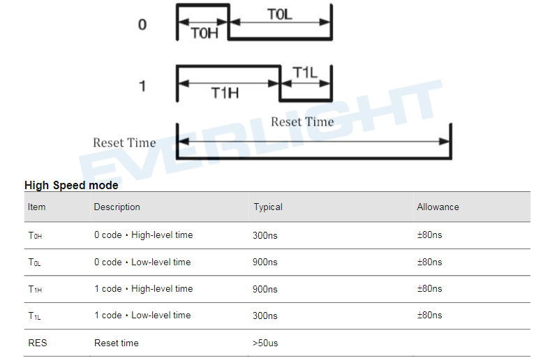 Figure1. Timings waveform and Requirements
First, let’s remind ourselves how an RGB color is represented digitally. An RGB color is represented with three bytes, each byte per channel: one byte for red, one byte for green and last byte for blue color, making a total of 24 bits. The MSB byte is read and LSB byte is blue color.
Now, back to the waveform and table above. These sources of information tells us that for each bit of the 24 bits of data needs a pulse whose period is 1200ns, and for bit 1, we need a PWM duty cycle of 75% (900/1200), and for bit 0 we need a PWM duty cycle of 25% (300/1200).
Since, I am not using PWM in this project to turn on these LEDs, which I will leave for next time, I need to find a way how to represent these 24 color bits with SPI data that I can send on the MOSI line from the MCU to the LEDs.
Assuming we need the first LED to be RED, then we need to send the following value: “0xEEEEEEEE8888888888888888” which is in binary: “1110111011101110111011101110111010001000100010001000100010001000 10001000100010001000100010001000“, and this is all to it when it comes to data representation. Now, we need to look at the data sequence requirements for each of the eight LEDs.
 Figure 2. Data Communication
The figure above, as per the datasheet, tells us that the first 24 bits is for the first LED and send 24 bits are for the second LED and so on till the last 24 bits which will be for the eighth LED. Again, in our case we are sending 96 bits instead of 24 bits for each LED! Also note that data is clocked starting from the MSB bit.
The code below is a VHDL driver module to drive these eight addressable Leds:
library ieee;
use ieee.std_logic_1164.all;
use ieee.std_logic_unsigned.all;
use ieee.numeric_std.all;


entity LedsDriver is
port(
      rst_n            : in std_logic;
      clk              : in  std_logic;
      Pulses_En        : in std_logic;  --used to enable pulses data
      ColorPulse       : out std_logic);
end LedsDriver;

architecture rtl of LedsDriver is

type LedColorsArray is array (0 to 7) of std_logic_vector(23 downto 0);
signal RGBArray  : LedColorsArray;

signal NewPWMcycle: std_logic;
signal enable: std_logic;
signal cntLimit: integer range 0 to 106;

constant Cnt1Limit: integer:=77;
constant Cnt2Limit: integer:=26; -
constant PWMperiod: integer:=106;

signal LedColorsig:  std_logic_vector(23 downto 0);

signal Pulses_En_Dly1: std_logic;
signal Pulses_En_Dly2: std_logic;

begin

--------------------------------------------------------------------------------------------------------------------------------------------------
--This process generates 24 PWM cycle: Each cycle may have different duty cycle than the
--previous of next cycle. This depends on the individual color bit
--------------------------------------------------------------------------------------------------------------------------------------------------
 PROC1: process(clk)
 variable PWMperiod_Cnt: integer range 0 to 106; --3/--106;  -- PWM period per cycle
 begin
      if rising_edge(clk) then
  	 if(rst_n='0') then
           PWMperiod_Cnt:=0;
           NewPWMcycle<='0';
         else
           PWMperiod_Cnt:= PWMperiod_Cnt+1;
             if((PWMperiod_Cnt>=0) AND (PWMperiod_Cnt<=CntLimit)AND(enable='1'))then
       		ColorPulse<='1';
      	        NewPWMcycle<='0';
  	     elsif((PWMperiod_Cnt>CntLimit) AND (PWMperiod_Cnt<PWMperiod)AND(enable='1'))then
		ColorPulse<='0';
		NewPWMcycle<='0';
	     elsif((PWMperiod_Cnt=PWMperiod)AND(enable='1')) then
		ColorPulse<='1';
	        PWMperiod_Cnt:=0;
		NewPWMcycle<='1';      -- is ON for only one clock cycle
	     elsif(enable='0') then
		ColorPulse<='0';
		NewPWMcycle<='0';
		PWMperiod_Cnt:=0;
	     end if;
	   end if;
         end if;
end process;


 ------------------------------------------------------------------------
 --This process keeps track of bits and bytes for each color data packet:
 --each color data packet is: 8 bytes and bit of this packet needs to be
 -- assigned a PWM duty cycle. if bit is equal to zero, duty cycle is 24%
 -- and if the bit is 1, it has a duty cycle equal to 72%
 -----------------------------------------------------------------------
PROC2: process(clk)

 variable Bitindex: integer range 0 to 24;
 variable Byteindex: integer range 0 to 8;

 begin
      if rising_edge(clk) then
	 if(rst_n='0') then
            Bitindex:=0;
	    Byteindex:=0;
	    enable<='1';
	 else
	    Pulses_En_Dly1<=Pulses_En;
	    Pulses_En_Dly2<=Pulses_En_Dly2;
		if((Pulses_En='1') AND (Pulses_En_Dly1='0')) then
	           enable<='1';
		   Bitindex:=0;
		   Byteindex:=0;
		   LedColorsig<="000000000000000001111111";
	         end if;

		if(NewPWMcycle='1') then  --is on for only one clock cycle
		    Bitindex:=Bitindex+1;
	         end if;

	        if(Bitindex=24) then
                  Bitindex:=0;
		  Byteindex:=Byteindex+1;
		end if;

		if(Byteindex=8) then
                  Byteindex:=0;
                  enable<='0';
		end if;

	       if(RGBArray(Byteindex)(Bitindex)='1')AND(enable='1') then
		 CntLimit<=Cnt1Limit;
	       elsif(RGBArray(Byteindex)(Bitindex)='0')AND(enable='1') then
		 CntLimit<=Cnt2Limit;
	      end if;
       end if;
  end if;
end process;

 RGBArray(0)<=LedColorsig;
 RGBArray(1)<=LedColorsig;
 RGBArray(2)<=LedColorsig;
 RGBArray(3)<=LedColorsig;
 RGBArray(4)<=LedColorsig;
 RGBArray(5)<=LedColorsig;
 RGBArray(6)<=LedColorsig;
 RGBArray(7)<=LedColorsig;

 end rtl;
References
[1]. Everlight Datasheet, https://www.everlight.com/file/ProductFile/19-237-R6GHBHC-A04-2T.pdf
