
Project Overview
In this project, I will demonstrate how to implement Amplitude Modulation (AM) demodulation using a Direct Digital Synthesizer (DDS) in Xilinx Vivado. The design focuses on digital signal processing techniques implemented on FPGA hardware. For the demonstration purpose, we are demodulating the AM single tone we modulated in the previous project: a 1KHz single tone modulated with 1600KHz carrier frequency.
This project demonstrates how AM demodulation can be implemented digitally using DDS
and FPGA technology. Understanding both the mathematical and digital implementation
aspects ensures accurate recovery of the original message signal.
This project is useful for understanding digital communication systems and FPGA-based signal processing. The concepts demonstrated here can be applied to software-defined radio (SDR), wireless communication systems, and real-time signal processing applications.
Objectives
- Understand the principles of AM modulation and demodulation.
- Generate a carrier signal using DDS.
- Demodulate an AM signal using digital techniques.
- Implement and simulate the design in Xilinx Vivado.
Tools and Technologies
- Xilinx Vivado Design Suite
- FPGA (Xilinx-based)
- VHDL for hardware description
- DDS IP Core configuration
Project Overview
In this project, I will demonstrate how to implement Amplitude Modulation (AM)
demodulation using a Direct Digital Synthesizer (DDS) in Xilinx Vivado.
The design focuses on digital signal processing techniques implemented
on FPGA hardware.
Objectives
- Understand the principles of AM modulation and demodulation.
- Generate a carrier signal using DDS.
- Demodulate an AM signal using digital techniques.
- Implement and simulate the design in Xilinx Vivado.
Tools and Technologies
- Xilinx Vivado Design Suite
- FPGA (Xilinx-based)
- Verilog or VHDL for hardware description
- DDS IP Core
Digital AM Demodulation
In digital AM demodulation, the incoming AM signal is sampled and represented as digital values. The FPGA multiplies the digitized signal with a DDS-generated carrier and applies a digital low-pass filter to recover the message signal.
- Sampling: Convert the AM signal into discrete-time digital values using an ADC.
- Carrier Generation: Generate a reference carrier using DDS.
- Multiplication: Multiply the digital AM signal with the carrier.
- Filtering: Remove high-frequency components using a digital low-pass filter: an FIR was used in our project.
- Output: The resulting signal represents the recovered message.
Mathematics of AM Demodulation
The AM signal can be represented as:
Where:
- Ac = carrier amplitude
- fc = carrier frequency
- m(t) = message signal
To demodulate digitally, multiply the AM signal with a locally generated carrier:
Using the identity cos²(x) = (1 + cos(2x))/2:
After low-pass filtering, high-frequency terms are removed:
The original message is recovered by scaling factor K:
In discrete-time digital implementation:
s[n] = sampled AM signal
c[n] = digital carrier from DDS
y[n] = s[n] * c[n]
m[n] ≈ Scaler * LPF{y[n]}
Implementation in Vivado with VHDL
The AM demodulation process is implemented by multiplying the received AM signal with a locally generated carrier produced by a DDS. The resulting signal is then passed through a low-pass filter to extract the original message signal.
To demonstrate the outcome of this project, ee are using the AM modulated signal we generated in our previous project: It is a 1kHz message signal modulated with a 1600KHz carrier frequency. Below are the steps to follow to recover our message signal:
-
- Configure a new DDS to generate a carrier frequency of 1600KHz.
- Using a multiplier IP Core, Multiply the AM modulated signal with the generated carrier signal of 1600KHz.
- Create an low pass FIR filter to filter the signal obtained in step 2 above. Refer the FIR project I discussed previously to see how to create a new FIR for this project. The FIR I created for this project has the following requirements:
- Sampling Frequency (fs): 500 kHz
- Passband Frequency (Fpass): 10 kHz
- Stopband Frequency (Fstop): 20 kHz
- Passband Ripple (Apass): 1 dB
- Stopband Attenuation (Astop): 60 dB
Below is a copy of the VHDL code:
AM Demodulator – VHDL Top-Level Design
library ieee;
use ieee.std_logic_1164.all;
use IEEE.STD_LOGIC_SIGNED.ALL;
use ieee.numeric_std.all;

Library UNISIM;
use UNISIM.vcomponents.all;

entity AM_DeModulator_TopLevel is
  port (
    clk_p         : in  STD_LOGIC;
    clk_n         : in  STD_LOGIC;
    reset         : in  STD_LOGIC;

    Dac_Out       : out std_logic_vector(11 downto 0);
    ChipSeclect_n : out STD_LOGIC;
    WriteEnable   : out STD_LOGIC
  );
end AM_DeModulator_TopLevel;

architecture behavioral of AM_DeModulator_TopLevel is

signal clk200MHz                : std_logic;
signal clk400MHz                : std_logic;
signal locked_Sig               : std_logic;
signal DDS0_tvalid_out          : std_logic;
signal CarrierFrequency         : std_logic_vector(15 downto 0);

-- (code unchanged, preserved exactly as provided)

----------------------------------------------------------------
--This Process generates 500 KHz clock to be used by FIR
--signal valid input.
----------------------------------------------------------------
process(clk200MHz,reset)
    variable cnt : integer range 0 to 199 := 0;
begin
    if reset = '1' then
        cnt           := 0;
        FIR_Valid_in <= '0';

    elsif rising_edge(clk200MHz) then
        if cnt = 199 then
            cnt := 0;
            FIR_Valid_in <= not FIR_Valid_in;
        else
            cnt := cnt + 1;
        end if;
    end if;
end process;

end behavioral;
Simulation Results
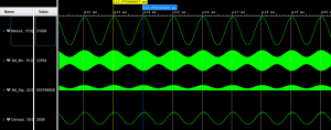 Figure 1: Demodulation simulation with Vivado
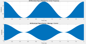 Figure 2: Simulation in Matlab
Measurements on the Oscilloscope
12 bits DAC: AD5445 was used to display the AM modulated and demodulated signals. It is a 12 bits DAC with up to 20.4 MSPS bandwidth.
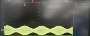 Figure 3: 1KHz AM modulated signal
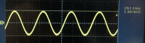 Figure 4: 1KHz AM Demodulated signal
Conclusion
This project provides hands-on experience with AM demodulation and DDS implementation using FPGA tools. It demonstrates how traditional communication techniques can be efficiently implemented using modern digital hardware.
Source Code
For a complete copy of the source code, please send me a message or send me a request in the comments section below. I hope you will find this tutorial helpful, and I would really appreciate any feedback or comments.
Author: Farid M
