
This tutorial is dedicated to Mr. Patrick Leung. It was him who taught me the very basics of VHDL and the fundamentals of digital design. It was with him that I found my passion in VHDL, digital design and engineering in general. You will be always remembered, Mr. Leung!
This tutorial is about implementing a 4 stage pipelined 16×16 bits multiplier, instead of using one of the FPGA multipliers. It takes 4 clock cycles to yield a product from the very instant the multiplier inputs are latched by the D-flip flop.
Algorithm Implementation
These are the stages needed for implementing this 4 stages multiplier:
- We break the 16 bits of the multiplier and multiplicand into 4 bits nibbles.
- At the first clock cycles we generate all partial products.
- In the second clock cycle we sum all products generated from same multiplier nibble
- At the second stage we sum the first two partial products, and the last two partial products.
- at the fourth cycle, we sum up the two partial sums that we generated in third clock cycle.
The power point below summaries the algorithm steps described above. It was takes from Mr. Leung lectures slides in summer 2010.
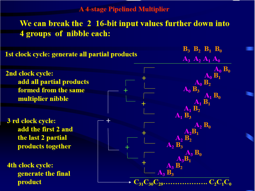 Figure1. summary of the 4 stage 16×16 pipelined multiplier, from Mr.Leung lectures
VHDL code
--Author: F. Mabrouk

LIBRARY ieee;
USE ieee.std_logic_1164.ALL;
USE ieee.numeric_std.ALL;
USE ieee.std_logic_unsigned.ALL;

ENTITY mult_system_4_stage IS PORT (

  clk	   :   IN  std_logic;							-- Multiplier clock
  en       :   IN  std_logic;							-- multiplier clocking enable,active high
  port_A   :   IN  std_logic_vector(15 downto 0); -- multiplicant input
  port_B   :   IN  std_logic_vector(15 downto 0); -- multiplier input
  port_out :   OUT std_logic_vector(31 downto 0)); -- product output

END mult_system_4_stage;

ARCHITECTURE assign3 OF mult_system_4_stage IS

SIGNAL SignFlag_0,SignFlag_1,SignFlag_2,SignFlag_3:std_logic; --define the type of input signflag

SIGNAL Reg_A: std_logic_vector(15 downto 0); -- data from input portA is stored in Reg_A
SIGNAL Reg_B: std_logic_vector(15 downto 0); -- data from input portB is stored in Reg_b

SIGNAL Reg1_A: std_logic_vector(15 downto 0); -- data from Reg_A is stored in Reg1_A afer checking 15th bit and taking 2's compliment
SIGNAL Reg1_B: std_logic_vector(15 downto 0); -- data from Reg_B is stored in Reg1_b afer checking 15th bit and taking 2's compliment


--Each generated product term is stored in a register
SIGNAL P0_Reg2, P1_Reg2,  P2_Reg2, P3_Reg2   : std_logic_vector(7 downto 0);
SIGNAL P4_Reg2, P5_Reg2,  P6_Reg2, P7_Reg2   : std_logic_vector(7 downto 0);
SIGNAL P8_Reg2, P9_Reg2,  P10_Reg2, P11_Reg2 : std_logic_vector(7 downto 0);
SIGNAL P12_Reg2,P13_Reg2, P14_Reg2,P15_Reg2  : std_logic_vector(7 downto 0);

--Sums are stored in registers3
SIGNAL Sum0_Reg3: std_logic_vector(19 downto 0);
SIGNAL Sum1_Reg3: std_logic_vector(19 downto 0);
SIGNAL Sum2_Reg3: std_logic_vector(19 downto 0);
SIGNAL Sum3_Reg3: std_logic_vector(19 downto 0);

BEGIN

MULTIPLIER: process(clk,en)

BEGIN

if ((clk'event and clk = '1') and (en = '1')) then

Reg_A<=port_A;
Reg_B<=port_B;

--Store value of portA input if positive, else take 2's complement of portA
-- and store it in Reg1_A register
if(Reg_A(15) = '1') then
Reg1_A<=(not Reg_A) + 1;
else
Reg1_A<=Reg_A;
end if;

--Store value of portB input if positive, else take 2's complement of portB
-- and store it in Reg1_B register
if(Reg_B(15) = '1') then
Reg1_B<=(not Reg_B) + 1;
else
Reg1_B<=Reg_B;
end if;

--Determine if product result will be positive or negative
if (((Reg_A(15) = '1') and (Reg_B(15) = '1') )OR ((Reg_A(15) = '0') and (Reg_B(15) = '0')))then
SignFlag_0 <= '0';
else
SignFlag_0 <= '1';
end if;

--**** partial products are generated and stored in registers2  *******************************
P0_Reg2<=Reg1_A (3  downto 0)*Reg1_B(3   downto 0); -- Multiplication Product of A0B0
P1_Reg2<=Reg1_A (3  downto 0)*Reg1_B(7   downto 4); -- Multiplication Product of A0B1
P2_Reg2<=Reg1_A (3  downto 0)*Reg1_B(11  downto 8); -- Multiplication Product of A0B2
P3_Reg2<=Reg1_A (3  downto 0)*Reg1_B(15  downto 12); -- Multiplication Product of A0B3
P4_Reg2<=Reg1_A (7  downto 4)*Reg1_B(3   downto 0); -- Multiplication Product of A1B0
P5_Reg2<=Reg1_A (7  downto 4)*Reg1_B(7   downto 4); -- Multiplication Product of A1B1
P6_Reg2<=Reg1_A (7  downto 4)*Reg1_B(11  downto 8); -- Multiplication Product of A1B2
P7_Reg2<=Reg1_A (7  downto 4)*Reg1_B(15  downto 12);-- Multiplication Product of A1B3
P8_Reg2<=Reg1_A (11 downto 8)*Reg1_B(3   downto 0); -- Multiplication Product of A2B0
P9_Reg2<=Reg1_A (11 downto 8)*Reg1_B(7   downto 4); -- Multiplication Product of A2B1
P10_Reg2<=Reg1_A(11 downto 8)*Reg1_B(11  downto 8); -- Multiplication Product of A2B2
P11_Reg2<=Reg1_A(11 downto 8)*Reg1_B(15  downto 12); -- Multiplication Product of A2B3
P12_Reg2<=Reg1_A(15 downto 12)*Reg1_B(3  downto 0);  -- Multiplication Product of A3B0
P13_Reg2<=Reg1_A(15 downto 12)*Reg1_B(7  downto 4);  -- Multiplication Product of A3B1
P14_Reg2<=Reg1_A(15 downto 12)*Reg1_B(11 downto 8);  -- Multiplication Product of A3B2
P15_Reg2<=Reg1_A(15 downto 12)*Reg1_B(15 downto 12); -- Multiplication Product of A3B3

SignFlag_1<=SignFlag_0;            -- here we propagate the number value sign

--Storing partial sums in Register 3, 20 bit adder
Sum0_Reg3<= ("000000000000"&P0_Reg2)+("00000000"&P1_Reg2&"0000")+
	   ("0000"&P2_Reg2&"00000000")+(P3_Reg2&"000000000000");

Sum1_Reg3<= ("000000000000"&P4_Reg2)+("00000000"&P5_Reg2&"0000")+
           ("0000"&P6_Reg2&"00000000")+(P7_Reg2&"000000000000");

Sum2_Reg3<= ("000000000000"&P8_Reg2)+("00000000"&P9_Reg2&"0000")+
	    ("0000"&P10_Reg2&"00000000")+(P11_Reg2&"000000000000");

Sum3_Reg3<= ("000000000000"&P12_Reg2)+("00000000"&P13_Reg2&"0000")+
	    ("0000"&P14_Reg2&"00000000")+(P15_Reg2&"000000000000");

SignFlag_2<=SignFlag_1;    -- here we propagate the number value sign

--final sum--
if(SignFlag_2='1') then
port_out<=(NOT (("00000000"&(("0000"&Sum0_Reg3) + (Sum1_Reg3&"0000")))+
		((("0000"&Sum2_Reg3) + (Sum3_Reg3&"0000"))&"00000000")) + 1);
else
port_out<=(("00000000"&(("0000"&Sum0_Reg3) + (Sum1_Reg3&"0000")))+
		((("0000"&Sum2_Reg3) + (Sum3_Reg3&"0000"))&"00000000"));
end if;

END IF;
END PROCESS MULTIPLIER;

END assign3;
Vivado Simulation
The code above was simulated with a test bench and it shows indeed that each multiplication takes 4 clock cycles from the very instant an input is latched (at rising edge.) You can verify these by looking a the timings below.
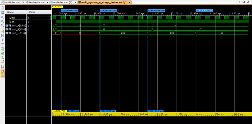 Figure2. Simulation results generated on Xilinix Vivado
If you like this tutorial, give us a like below and if you have any questions or feedback, feel free to drop us a message in the comment section.
